Section 2 - Installation
Page 10 90-8M0072763 eng JUNE 2012
Theft Deterrent System Kit Installation (Key Fob)
Guidelines for Installing Harnesses
Follow these guidelines when installing the harnesses:
• The maximum CAN bus length is 70 m (230 ft).
• The maximum length of a CAN bus drop (branch off the main harness) is 7 m (23 ft).
• The combined length of all drops cannot exceed 36 m (118 ft).
• Locate an appropriate path for routing the harness connections to their installation points.
• Inspect the routing path to ensure that the surfaces are free of any sharp edges or burrs that could cut the harness.
• Fasten and support the harness with clamps or cable ties along the routing path. A clamp or cable tie must be used within
25.4 cm (10 in.) from any connection and every 45.8 cm (18 in.) along the routing path if not housed in a rig tube.
• Ensure that all connections are tight and locked (if equipped with a lock mechanism).
• Seal all unused connectors with weather caps.
• Route the harness at least 1 m (3 ft 3 in.) from any device that produces electromagnetic interference (EMI), such as VHF
radio and radar equipment.
Precautions for Wiring and Harnesses
IMPORTANT: Refer to the following precautions to avoid damage to the electrical system when working on or around the
electrical harness or when adding other electrical accessories.
• Do not attempt diagnostics without the proper approved service tools.
• Do not puncture wires for testing (probing).
• Do not splice wires into the harness.
• Do not connect, network, tie into, switch, or sink source voltage or current from the wiring harnesses.
• Do not connect any type of communication or navigation equipment into the wiring harnessing other than at the designated
connection point.
• Install boat accessory equipment using an appropriate power source connection, such as a fuse panel or junction box
circuit breaker.
• Do not tap directly into any of the electrical wiring harnesses for a source of power.
Installing the Docking Station
1. Select a mounting location for the docking station that provides the following:
• The docking station must not be closer than 102 mm (4 in.) from any device that produces electromagnetic
interference (EMI), such as VHF radio and radar equipment.
• The docking station must be installed within 1.2 m (4 ft) of the TDS module. The docking station harness cannot be
extended. Refer to Wiring Connections.
• Ensure the mounting location affords accessibility from behind the dashboard.
2. Use a hole saw and cut a 54 mm (2‑1/8 in.) mounting hole for the docking station.
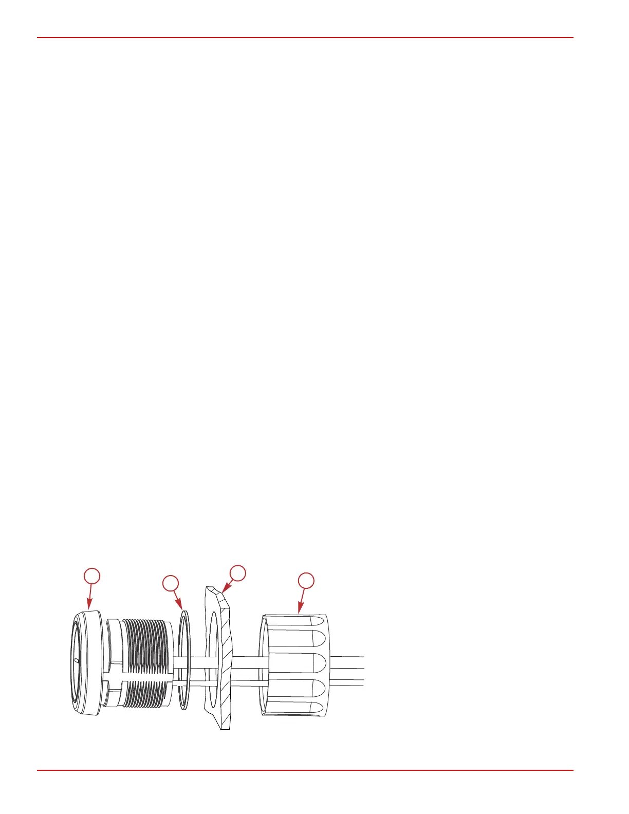
3. Place the gasket onto the docking station.
4. Place the docking station into the mounting hole. Secure with the retainer nut.
a - Docking station
b - Gasket
c - Mounting location
d - Retainer nut
 Loading...