Section 2 - Installation
Page 12 90-8M0072763 eng JUNE 2012
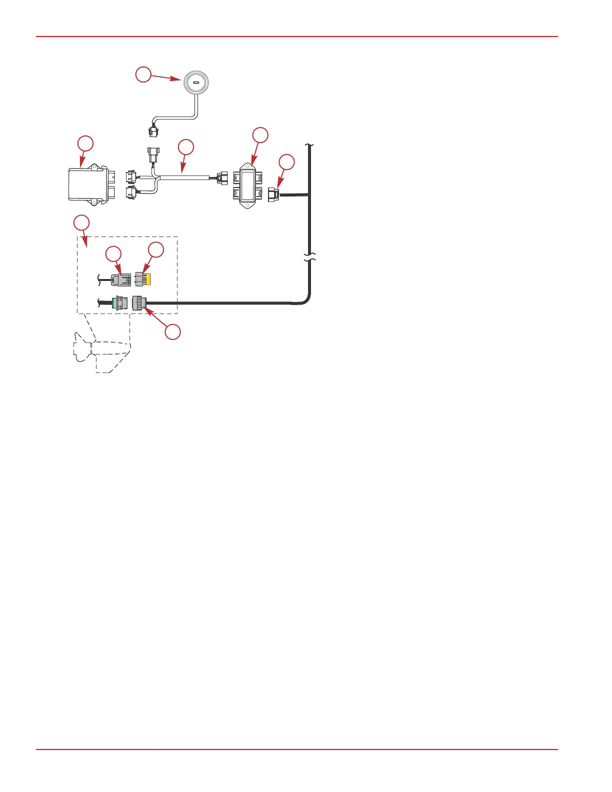
• Refer to the following wiring diagram for the proper wiring connections.
Single engine with existing 10 pin harness at the helm
a - Docking station
b - TDS wiring harness
c - Junction box
d - 10 pin existing harness
e - Termination resistor
f - 10 pin connector
g - 14 pin connector
h - Engine
i - TDS module
Boats without 10 Pin Harness at the Helm
• Plug the 10 pin connector (from the TDS wiring harness) into the junction box. Refer to the following wiring diagram. For
multiengine applications, it must be connected to the multiwake or VesselView display junction box.
• Remove the termination resistor from the 10 pin connector on the engine. Connect a SmartCraft 10 pin (one resistor) data
harness (blue) between the 10 pin connector on the engine and the junction box. Connect the end of the data harness
(which has the resistor) to the 10 pin connector on the engine. Refer to the following wiring diagram.
• Install the termination resistor into the junction box. Refer to the following wiring diagram.
• Plug the 8 pin connector (from the TDS wiring harness) into the 8 pin connector from the docking station. Refer to the
following wiring diagram.
• Plug both 12 pin connectors (from the TDS wiring harness) into the connectors on the TDS module. The connectors are
keyed to ensure correct orientation. Refer to the following wiring diagram.
 Loading...