Section 2 - Installation
90-8M0072763 eng JUNE 2012 Page 11
Installing the TDS Module
1. Select a mounting location for the TDS module that provides the following:
• Mount the TDS module in an area that stays relatively dry.
• The TDS module must be installed within 1.2 m (4 ft) of the docking station. The docking station harness cannot be
extended. Refer to Wiring Connections.
• If the TDS module is mounted on a vertical surface, orient the connectors towards the side or downward.
• Allow a minimum clearance of 10 cm (4 in.) for connector installation and removal.
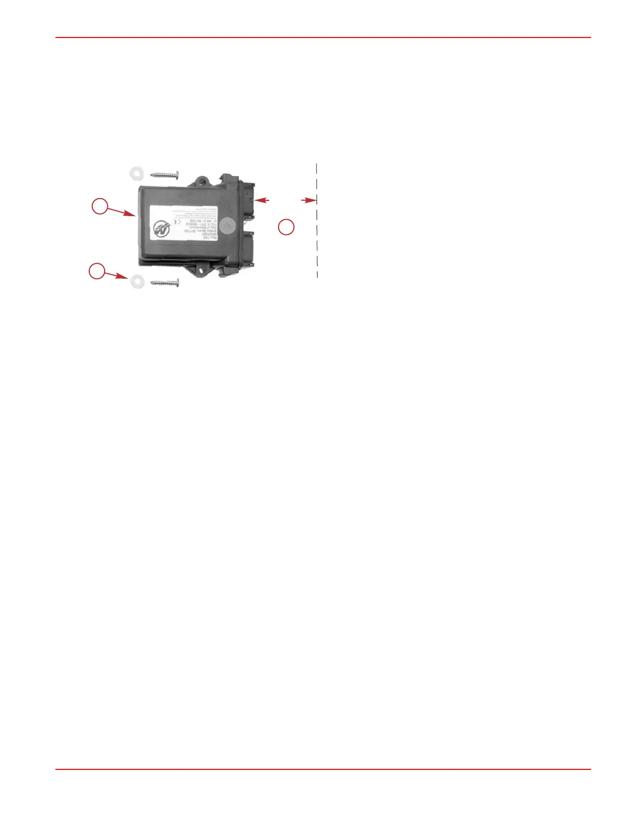
2. Fasten the module to a flat surface with the screws and flat washers provided.
a - TDS module
b - Minimum clearance for connector installation and removal
c - Mounting screws and flat washers (2)
Wiring Connections
Boats with Existing 10 Pin Harness at the Helm
• Plug the 10 pin connector (from the TDS wiring harness) into the junction box. Refer to the following wiring diagram. For
multiengine applications, it must be connected to the multiwake or VesselView display junction box.
• Plug the existing 10 pin connector (located at the helm) into the junction box. Refer to the following wiring diagram.
• Plug the 8 pin connector from the docking station into the 8 pin connector on the TDS wiring harness. Refer to the following
wiring diagram.
• Plug both 12 pin connectors (from the TDS wiring harness) into the connectors on the TDS module. The connectors are
keyed to ensure correct orientation. Refer to the following wiring diagram.
 Loading...