Section 2 - Installation
90-8M0072763 eng JUNE 2012 Page 15
1. Locate an area under the deck of the vessel to mount the two antennas less than 3 m (9 ft) from the mobile transceiver unit
(MTU). Use tape (not included) to temporarily retain the antennas to the underside of the deck. The antennas must have
an unobstructed view of the sky, and cannot be closer than 7.6 cm (3.0 in.) to each other.
2. Temporarily mount the mobile transceiver unit (MTU) in an area where there is easy access to the antenna cables, a
SmartCraft junction box, and a power source or accessory battery. The power source or accessory battery connection
must be uninterrupted.
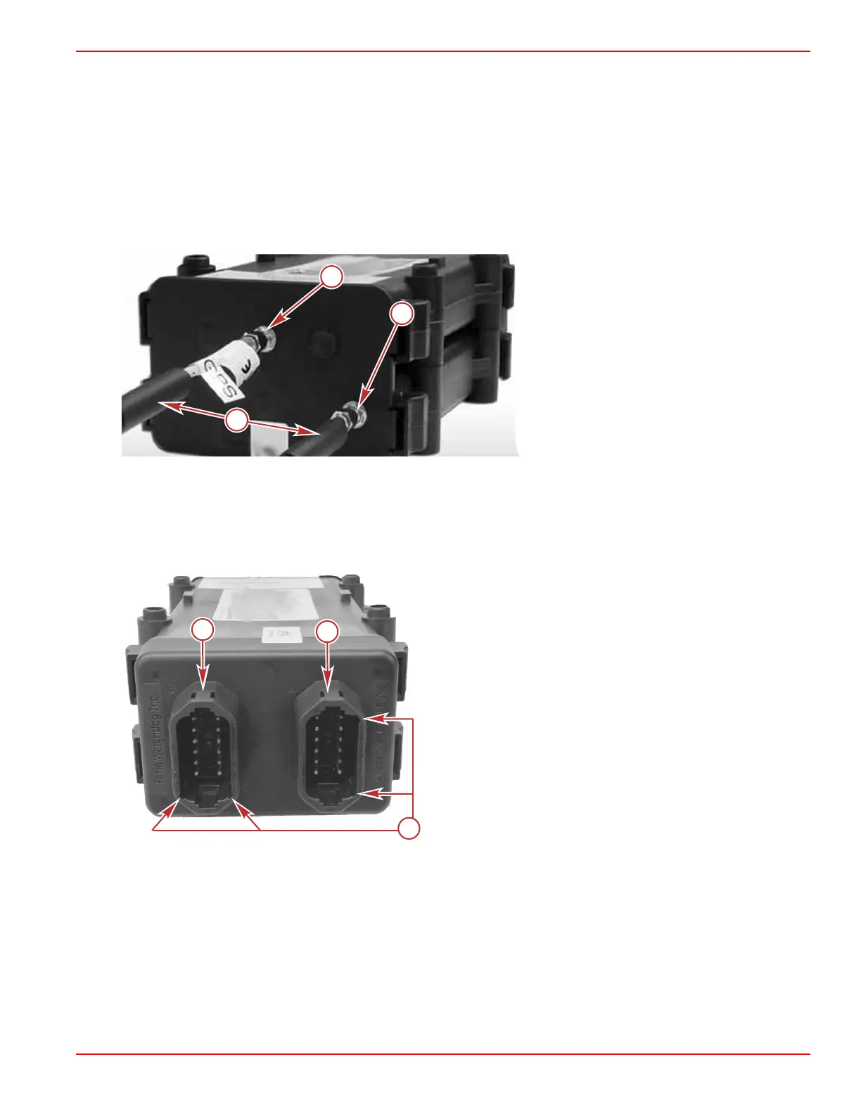
3. Install the shrink tube over the GPS antenna cable and Iridium satellite antenna cable ends.
4. Connect the GPS antenna cable to the J1 connector on the MTU and tighten securely. Do not use any tools to tighten this
connector. Do not apply heat to the shrink tube.
5. Connect the Iridium satellite antenna cable to the J3 connector on the MTU and tighten securely. Do not use any tools to
tighten this connector. Do not apply heat to the shrink tube.
a - GPS antenna connection
b - Iridium satellite antenna connection
c - Shrink tube
6. Connect the SmartCraft harness connector to the B connector on the MTU. Connect the other end of the harness to a
junction box.
7. Connect the power harness connector to the A connector on the MTU.
NOTE: The MTU connector ports are keyed specifically for the harness that it can accept. Do not force the harness
connectors onto the MTU. If installed incorrectly, the harness connectors can be forced into the wrong MTU connector port.
a - Power harness A connector
b - SmartCraft harness B connector
c - Harness connector key
8. Connect the power harness 4 pin connector onto the user interface connector.
9. Secure the red and black power harness terminals to an uninterrupted power source. Red is positive and black is negative.
 Loading...