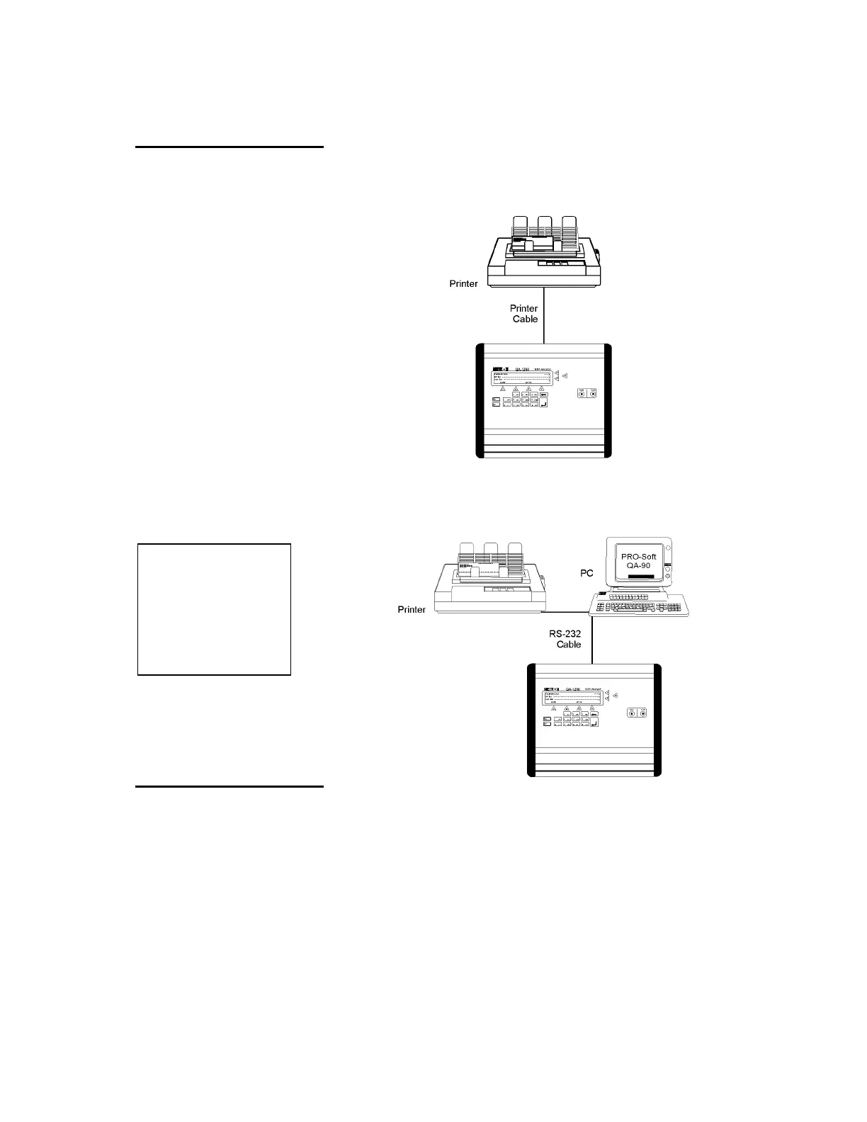
2.2 Setup
Equipment connection is as shown in the typical setup below. Attach
the printer cable to the 25-pin outlet port.
If ansur QA-1290 is being used, attach an RS-232C (null mo-
dem/data transfer configured) cable to the 9-pin D-sub outlet port lo-
cated at the rear of the QA-1290. Do not attach the printer cable to
the QA-1290. See below.
NOTE
Some RS-232C cables are
missing the connection between
the seventh and the eighth
wires in the cable. The cable
may still be called
NULL-modem, but it will not
work with the QA-1290. Refer to
the
ansur
QA-1290 Users
Manual for more information.
2.3 Connecting the Device
under Test
The connection of a mono-tube NIBP Analyzer and cuff is as shown
below. Tubing from the NIBP Analyzer is connected to the luer lock
on the Inlet Port, while the Cuff’s tubing is connected to the luer lock
on the Cuff Port.
2-2
 Loading...
