the message field in the same line.
3 LCD Display
Shows messages, test results and function menus.
4 Cuff Port
5. Inlet Port
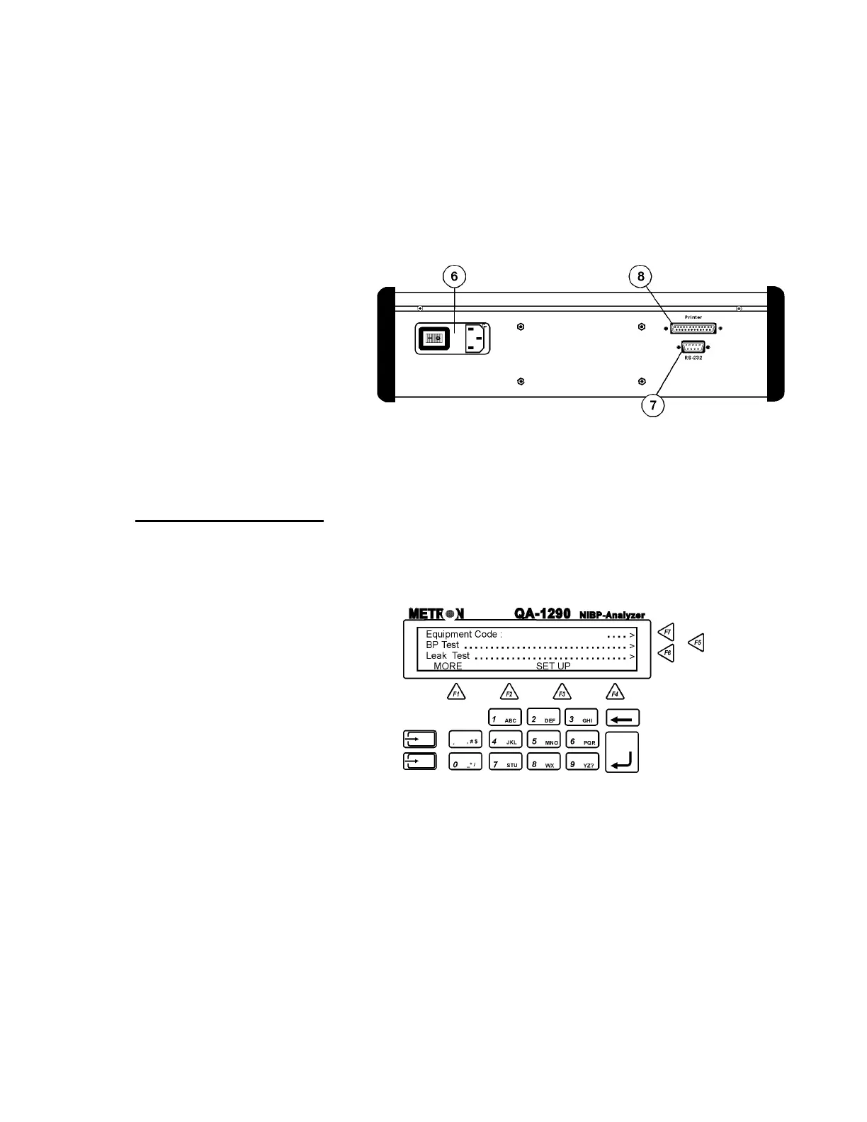
Rear Panel
6. Power Switch
and Mains
Power switch turns power ON and OFF. Mains con-
nects the QA-1290 to the 110 VAC - 240 VAC, 47/63
Hz power source.
7. RS-232 Port
9-pin D-sub for Remote Control.
8. Printer Port
Bi-directional 25 pin D-sub. Centronic output.
3.2 QA-1290’s Controls
QA-1290’s display, alphanumeric data entry keys, control keys and
programmable function keys provide flexibility and control in testing.
Operating them is very similar to operating a personal computer.
There are four text lines to each screen. The top three lines are used
for operator settings, system messages, and test status and results.
They are controlled by the F5, F6 and F7 keys, located to the right of
the display. Note, however, that these keys are active only when you
see the leading arrows (“. . . . . .>”) pointing to them. (See above)
The screen’s bottom line is a menu bar, controlled by function keys
F1 through F4 directly below the display. The menu is used for sys-
tem functions, such as PRINT or INFLATE, and for inter-screen
navigation, such as MORE and GO BACK.
3-2