8.4 Pneumatic System
The pneumatics and drivers are the QA-1290’s mechanical parts that
deal with the air pressure and pulse generation, and their electrical
drivers. This involves the electrically operated air valves that control
airflow with the cylinder and piston. These are, in turn, controlled by
the stepper motor in order to generate pulses. The system is used for
generating blood pressure pulses and to set up pressure for leakage test
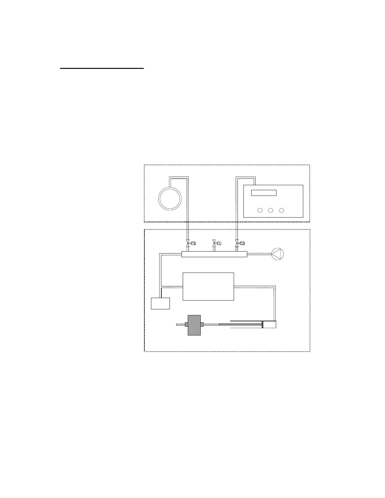
and over pressure test. The following diagram shows the QA-1290
pneumatic system’s functions.
Blood Pressure Monitor
Cuff
Internal "Cuff" (fixed volum)
Compressor
Valve Block
Pressure
Sensor
Ventilate
Valve
Cuff
Valve
Monitor
Valve
Step motor /
linear actuator
Pneumatic Cylinder
QA-1290
Device Under Test
QA-1290 Pneumatic System Drawing
A miniature compressor generates the pressure needed for the Leak and
Over-Pressure Cutoff Tests. It is also used during blood pressure simu-
lations for creating minor, rapid increases in pressure to simulate that
patient movement (i.e., when you press MOTION (F3)). Because the
compressor may have a little leakage that affects the leak test, a back
valve is inserted between the compressor and valve block.
The valve block has three valves to control the airflow. One connects
and disconnects the blood pressure monitors to the pneumatic system.
The second valve connects and disconnects the cuff to the pneumatic
8-5