Pin out:
Pin description:
Pin no: Signal Description
1 MA1 Winding 1 on step motor
2 n.c.
3 MB1
Winding 1
on step motor
4 MA2 Winding 2 on step motor
5 n.c.
6 MB2
Winding 2
on step motor
2. Magnet valves
Pin out:
Pin description magnet valves:
Pin no: Signal Description
1 +24V +24V after filter
2 VALVE1-3 Active LOW (GND)
3. Mini Compressor
Pin out:
Pin description:
Pin no: Signal Description
1 +24V +24V after filter
2 COMPRESSOR Compressor output, active LOW
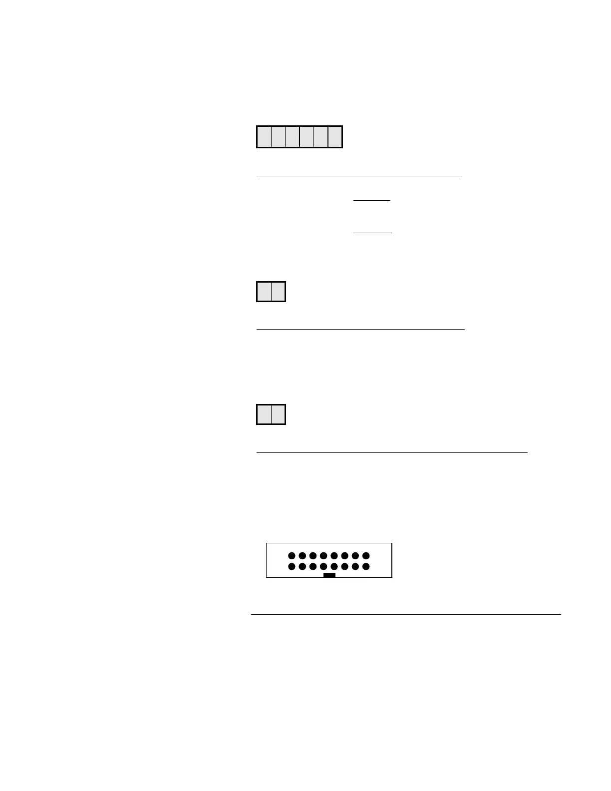
4. Processor Board
A 16 conductors ribbon cable is used for all communication be-
tween the QA-1290 board and processor board. The connector is
configured as follows:
2
1
16
15
P250 pin no: Voltage / pin I/O Signal name Function
1 +5 ---
2 +5 ---
3* OP3 O STEP- Step motor, step pulses
4 PA1 I AD_EOC
5 PA3 O MOSI SPI data out
6 PA4 O SCK SPI clock
7 PA5 O AD_CS Chip Select for A/D
8-7