Additional requirements for the servo drives concerning the UL approval Page 22
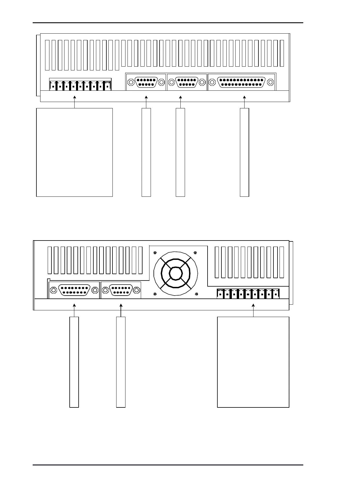
[X1] I/O[X10] IN[X11] OUT
[X9]
[X9]: Power Supply
L: mains phase 230VAC
N: mains neutral conductor
ZK+: pos. DC bus voltage
ZK-: neg. DC bus voltage
BR-INT: intern brake chopper
BR-CH: brake chopper
PE: ground conductor from
mains
+24V: 24VDC
GND24V: GND 24VDC
[X11]: Incremental encoder output
[X10]: Incremental encoder input
[X1]: I/O interface
Figure 2: Servo drive ARS 2102 SE: Top view
[X2A] RESOLVER
[X6]
[X2B] ENCODER
[X6]: Motor Connection
BR-: holding brake
BR+: holding brake
PE: inner shield
MT-: motor sensor
MT+ motor sensor
PE: motor ground conductor
W: motor phase 3
V: motor phase 2
U: motor phase 1
[X2A]: Connection for the resolver
[X2B]: Connection for the encoder
Figure 3: Servo drive ARS 2102 SE: Bottom view
Mounting Instructions „Servo drives ARS 2100 SE“ Version 5.0
 Loading...

