Page 49
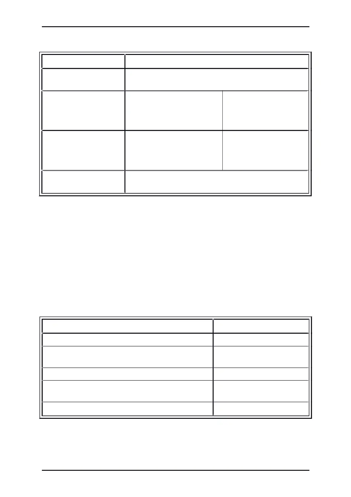
Table 27: Technical data: Analogue inputs and outputs [X1]
Analogue inputs/outputs Values
High-resolution
analogue input, AIN 0
10 V input range, 16 Bit, differentially,
< 250 µs delay time
Analogue input, AIN 1 Optionally, this input can also be
parameterised as digital input DIN
AIN 1 with a switching threshold at
8 V
10 V, 10 Bit, single ended,
< 250 µs delay time
Analogue input, AIN 2 Optionally, this input can also be
parameterised as digital input DIN
AIN 2 with a switching threshold at
8 V
10 V, 10 Bit, single ended,
< 250 µs delay time
Analogue outputs, AOUT 0
and AOUT 1
10 V output range, 10 mA,
9 Bit resolution, f
Limit
> 1 kHz
4.6.6 Incremental encoder input [X10]
The input supports all common incremental encoders.
For example encoders corresponding to the industry standard ROD426 by Heidenhain or encoders
with single-ended TTL outputs as well as open collector outputs.
Alternatively, the A and B encoder signals are interpreted by the device as pulse-direction signals, so
that the servo drive can also be driven by stepping motor control boards.
Table 28: Technical data: Incremental encoder input [X10]
Parameter Values
Parameterisable line count 1 – 2
28
lines/revolution
Trace signals: A, #A, B, #B, N, #N iIn accordance with RS422-
specifikation
Max. input frequency 1000 kHz
Pulse direction interface: CLK, #CLK, DIR, #DIR, RESET,
#RESET
In accordance with RS422-
specifikation
Supply output 5 V, max. 100 mA
Product Manual „Servo drives ARS 2100 SE“ Version 5.0