EasyManua.ls Logo

Metronix ARS 2102 SE - Connection Notes [X2 B]; Figure 19: Pin Assignment: Analogue Incremental Encoder [X2 B]; Figure 20: Metronix Servocommander: Angle Encoder Settings [X2 B]

Default Icon
156 pages
Print Icon
To Next Page IconTo Next Page
To Previous Page IconTo Previous Page
Loading...
Page 95
8.7.5 Connection notes [X2B]
Output of the analog incremental
encoder interface at the motor
D-SUB connector
at X2B
Shield connector
SK 14
Cable shield
(optional)
Connector housing
2
3
4
5
9
10
11
1
12
6
7
8
13
14
15
1
9
8
15
COS_Z0
#COS_Z0
#SIN_Z1
#SIN_Z0
SIN_Z1
#COS_Z1
COS_Z1
#R
SIN_Z0
R
GND
US
U_SENS-
U_SENS+
TEMP+
TEMP-
Male
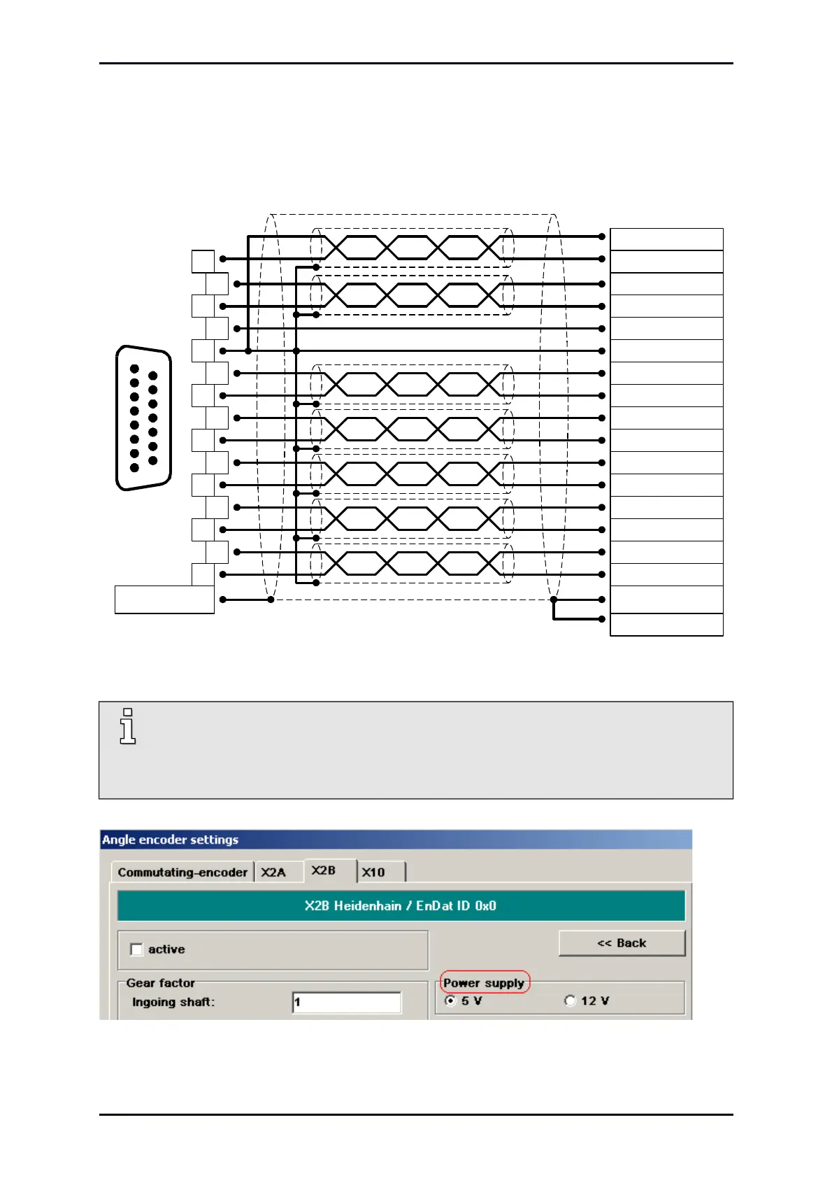
Figure 19: Pin assignment: Analogue incremental encoder [X2B]
In case of wrong activated voltage supply, the encoder can be destroyed! Make sure the
correct supply voltage is activated, before connected to [X2B]!
Therefore, start the parameterisation software Metronix ServoCommander
®
and select
Parameters/Device parameters/Angle encoder settings.
Figure 20: Metronix ServoCommander
®
: Angle encoder settings [X2B]
Product Manual „Servo drives ARS 2100 SE“ Version 5.0

Table of Contents

Other manuals for Metronix ARS 2102 SE

Related product manuals