14 1 X 78 en
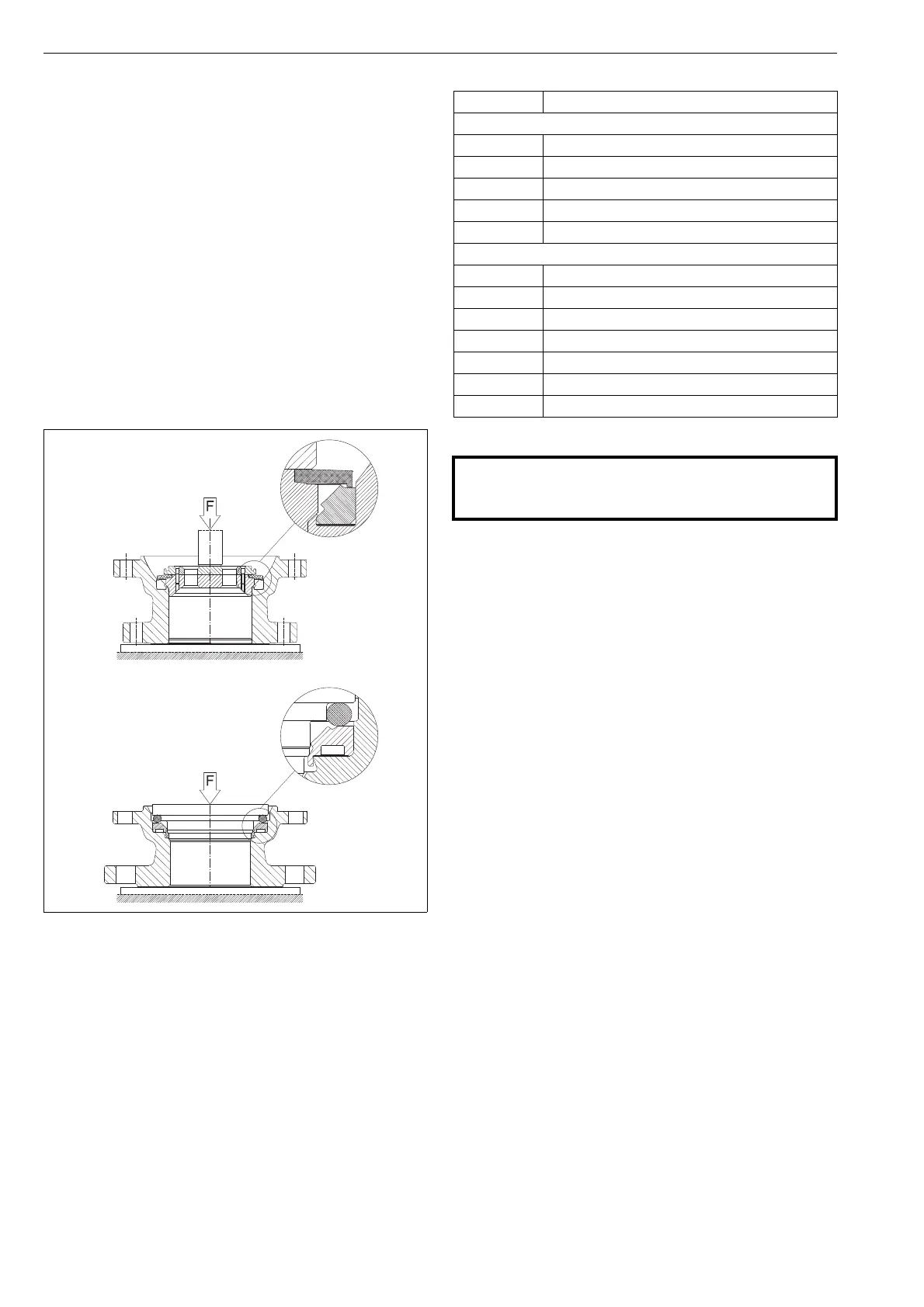
4.9.3 Locking of the seat
A seat locking tool (can be ordered from the manufacturer)
and a hydraulic press with suitable capacity are needed for
locking.
Mount the seat with the back seal as described in the
earlier section.
Mount the locking tool carefully over the seat, see
Fig. 33.
Place the valve body/body cap on the bed of the
press. The bed surface must be level and non-
scratching.
Align the valve and locking tool properly with the
piston of the press.
Press the tool to lock the seat. See Table 6 for press-
ing forces.
Remove the body/body cap from the press and con-
tinue the reassembly as described in the earlier sec-
tion.
5 TESTING THE VALVE
Test the valve’s body pressure after reassembly.
Test the pressure in accordance with an applicable standard. Use
the pressure required by the pressure class or the flange bore. Keep
the valve in the half open position during the test.
If the tightness of the closure member is also to be tested,
please contact the manufacturer.
If testing according to the UOP 671 specification is required,
follow appropriate instructions.
Fig. 33 Locking of the seat
Table 6 Pressing forces for seat locking
Valve size Force (kN)
TA construction
02 70
03 140
04 160
06 250
08 370
GA construction
01 55
1H 75
02 130
03 110
04 125
06 200
08 400
CAUTION:
Pressure testing should be carried out using equipment
conforming to the correct pressure class!
 Loading...