8 1 X 78 en
The gland packing (69) must be changed if leakage occurs
even after the hex nuts (18) have been tightened. The V-
ring gland packing must be tightened with care because
excess force may damage the V-rings.
Make sure that the valve is not pressurized.
Detach the actuator and bracket according to the
instructions in section 4.4.
Remove the key (10).
Remove the hexagon nuts (18), disc spring sets (150,
one stud (14) and retaining plates (42) and gland (9).
Remove the packing rings (69) from around the shaft
using a knife or some other pointed instrument
without scratching the surfaces.
Clean the packing ring counterbore.
Place the new packing rings (69) over the shaft (5).
The gland follower may be used for pushing the rings
into the counterbore. Do not damage packing rings in
the shaft keyway. Please note that the support ring
(67) may come off as you remove the packing in GA
construction 2"-8" (type code 5th sign). It should be
placed back in its position before installing the new
packing. See Fig. 17. Screw down the removed stud.
Deform the packing rings first by tightening the
gland nuts without disc springs to the torque Tt, see
the value from Table 1.
Remove the gland nuts, mount the retaining plates
(42) and the removed stud in sizes 2"-8" and place the
disc spring sets (150) on the gland studs. Tighten the
nuts (18) so that the disc springs are compressed to
the height Hc, see Table 1. Lock the nuts with locking
compound e.g. Loctite 221. See Fig. 16.
Check leakage when the valve is pressurized and
tighten the nuts (18) more if needed.
4.3 Repairing a jammed or stiff valve
without removing it from the pipeline
Jamming or stiff function may be caused by a flow medium
clogging the seat (7, 25) and the ball (3). The ball and the seats
can be cleaned without removing the valve from the pipeline
by turning the ball to a partly open position and flushing the
pipes.
If this does not help, follow the instructions below.
4.4 Detaching the B series actuator
It is usually easiest to detach the actuator and support
equipment before removing the valve from the pipeline. If
the package is small or not easily accessible, it is better to
remove the entire package at the same time.
Please note that the ball seats can be replaced without
detaching the actuator.
Fig. 16 Installing the retainer plates
Table 1 Tightening of the gland packing
Valve size A (mm) Hc (mm) Tt (Nm)
01" 20 20.4 5
1 1/2" 20 20.1 5
02", 03" 20 28.9 10
04" 25 28.8 12
06" 35.5 37.7 14
08" 35.5 37.6 20
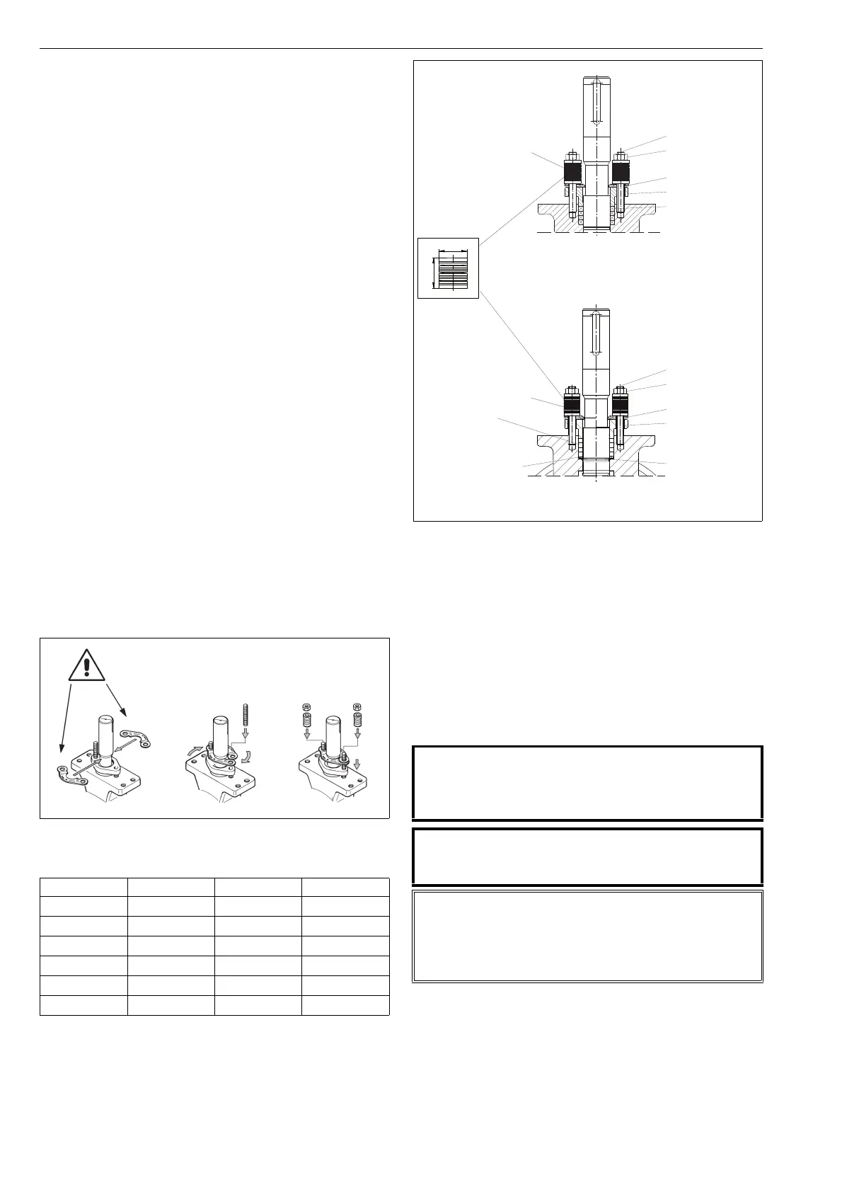
Fig. 17 Packing
CAUTION:
When handling the valve or the valve package as a
whole, bear in mind the weight of the valve or the
entire package!
CAUTION:
Do not detach a spring-return actuator unless a stop-
screw is carrying the spring force!
NOTE:
Before dismantling, carefully observe the position of the
valve with respect to the actuator and positioner/limit
switch so as to make sure that the package can be prop-
erly re-assembled.
1" - 8" TA / 1" - 1 1/2" G
A
H
c
2" - 8" GA
retaining plate (42)
stud (14)
hexagon nut (18)
disc spring set (150)
packing (69)
V-ring set or
graphite packing
gland (9)
retaining plate (42)
stud (14)
hexagon nut (18)
disc spring set (150)
packing (69)
(V-ring set or
graphite packing)
gland (9)
locking wire (51)
support ring (67)
 Loading...