1 X 78 en 3
1GENERAL
1.1 Scope of the manual
This manual provides the essential information on the use
of XT/XA and XB/XC series seat supported ball valves. For
further information on actuators and other instruments,
which are covered only briefly, please refer to separate
manuals on their installation, use and maintenance.
1.2 Valve description
XT/XA series valves are full bore and XB/XC series valves are
reduced bore flanged ball valves. The valves are either
metal or soft seated. Valves have two-piece bodies with
bolted body joints, except the bodies of the 3", 4" and 6"
valves comprise a single part. The ball and the shaft are sep-
arate parts and a shaft blow-out is prevented by a separate
thrust ring/pin and retaining plates.
A spline driver transmitting the shaft torque to the ball con-
nects the shaft with the ball. In 1" and 1 1/2" valves the shaft
directly drives the slot in the ball (no separate driver).
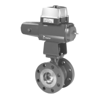
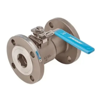
The valve is tight in both flow directions. Tightness is based
on pipe pressure, i.e. the pressure differential over the valve
forces the ball against the downstream seat. The arrow in
Figs. 1, 2 and 3 shows the recommended flow direction
with H and G seat construction.
The construction of the valves may vary in accordance with
customers’ wishes. The construction details are indicated in
the type code in the identification plate. For more informa-
tion about the type code, see Section 12.
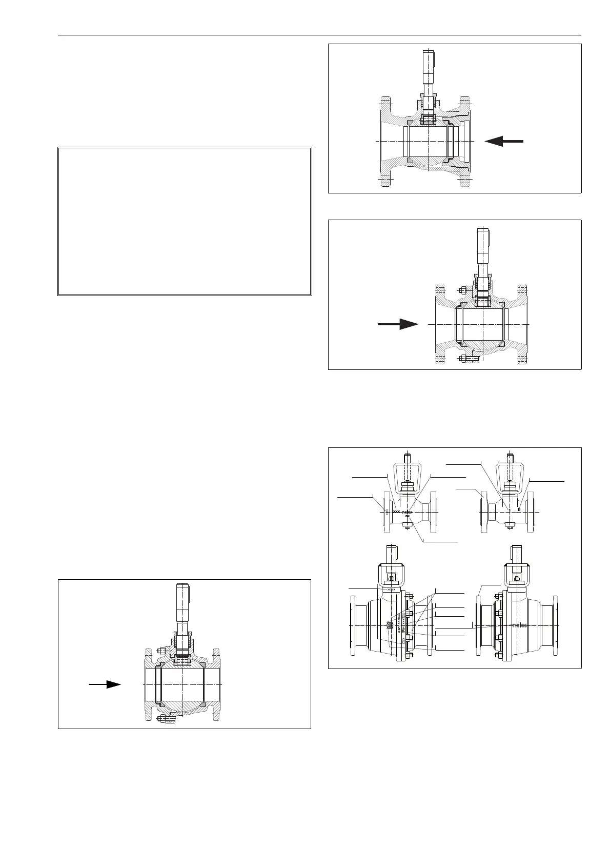
1.3 Valve markings
Body markings are cast or stamped on the body (see Fig. 4).
The identification plate (Fig. 5) is on the valve flange.
NOTE:
As the use of the valve is application-specific, a number of
factors should be taken into account when selecting the
application. Therefore, some of the situations in which the
valves are used are outside the scope of this manual.
If you are uncertain about use of the valve or its suitability
for your intended purpose, please contact Metso for more
information.
For valves in oxygen service, please see also the separate
installation, maintenance and operating instructions for
oxygen service (see Metso document id:10O270EN.pdf)
Fig. 1 Construction of an XT/XA-series valve,
sizes 1"-8"
Recommended
flow direction for
valves with H seat
Fig. 2 Construction of an XB/XC series valve, sizes 3", 4" and 6"
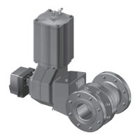
Fig. 3 Construction of an XB/XC series valve, size 8"
Fig. 4 Valve markings
Recommended
flow direction for
valves with H or G
seat
Recommended
flow direction for
valves with H or G
seat
Batch number
Nominal size
Id plate
Body material
Batch number
Id plate
Foundry’s
Nominal size
Pressure class
Body material
Manufacturer’s
Casting no.
Foundry’s mark
mark
Manufacturer’s
mark
mark
Casting no.
 Loading...