1 X 78 en 9
Close and detach the actuator pressure supply and
disconnect the control cables and pipes.
Loosen the bracket screws.
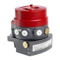
Detach the actuator from the valve with an extractor
that can be ordered from the manufacturer. See Sec-
tion 8 ’Tools’.
Remove the bracket.
4.5 Removing the valve from the pipeline
Make sure that the pipeline is empty and unpressu-
rized and that there is no medium flowing to the
pipeline while the valve is being serviced.
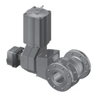
Carefully attach the ropes, loosen the pipe flange
screws and lift the valve using the ropes. Make sure that
you lift the valve correctly. See also Fig. 12.
4.6 Dismantling the valve
4.6.1 Sizes 1" - 8" (XT/XA), 8" (XB/XC)
Place the valve so that the body’s hexagon nuts (16) /
body cap (2) point upwards. Use a surface that does
not damage the flanges.
Mark the body halves for correct orientation during
reassembly.
Loosen the gland nut (18).
Turn the ball to the closed position.
Loosen the body nuts (16).
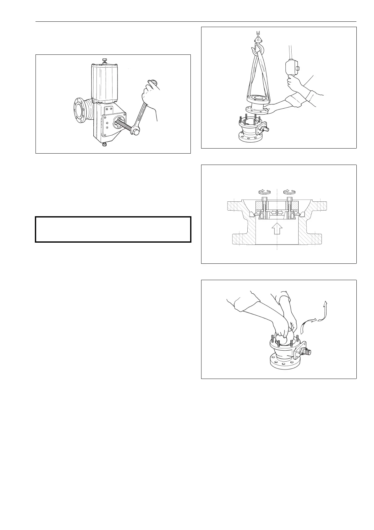
Remove the body cap (2) from the valve. Should the
ball seat (7, 25) not stay on the body cap, keep it
from falling while you are lifting it out by putting
your fingers under the body cap (small sizes) or in
the flow bore (large sizes). Watch out for your hand!
Lower the body cap onto the surface in a standing
position, i.e. onto its flange. See Fig. 19.
Remove the seat (7, 25) from the body cap making
sure that it is not damaged during the operation. If the
seat is of a locked type, use a special tool which can be
ordered from the manufacturer. See Fig. 20 and Sec-
tion 8 ’Tools’.
Remove the ball (3) from the body (1) by gripping
the edges of the flow bore (small sizes) or by passing
a rope through the bore (large sizes). To detach the
ball from the spline driver (4) in sizes 2"-8" or from
shaft/thrust ring (4) in sizes 1"-1 1/2", turn the ball to
the closed position before lifting. Make sure that the
ball is not damaged and put it onto a soft surface.
See Fig. 21.
Remove the key (10).
Remove the gland nuts (18), spring set (150), one
stud (14), retaining plates (42) and gland (9). Remove
Fig. 18 Detaching a B series actuator with an extractor
CAUTION:
Do not dismantle the valve or remove it from the pipe-
line while the valve is pressurized!
Fig. 19 Lifting the body cap
Fig. 20 Removing a locked seat
Fig. 21 Removing the ball from the body
 Loading...