MG-MINA/LINA/750-LFC GRID ASSEMBLY GUIDE
21
CAUTION: Do not use the 750-LFC’s middle GuideALinks when flying the 750-LFC below the
MG-MINA/LINA/750-LFC grid or when flying below another 750-LFC. Always use the front and rear
GuideALinks when flying the 750-LFC.
750-LFC Splay Angles
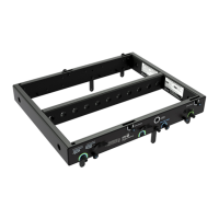
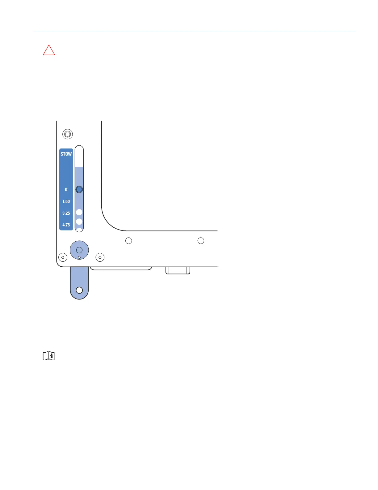
The front and rear GuideALinks attach at angles of 0, 1.5, 3.25 or 4.75 degrees, allowing curved 750-LFC arrays. Because
the cabinet’s front and rear GuideALinks are symmetrical, the curved arrays can also include cardioid configurations.
The labels next to the front and rear GuideALinks indicate the splay angle between cabinets (when the opposing links are set
to 0 degrees). As the links are moved down, the splay angle increases. To stow the GuideALinks, move them all the way up
to STOW and pin them.
NOTE: Curved 750-LFC arrays do not provide directionality for low-frequency content. The curved array
capability of the 750-LFC is provided to minimize unwanted high frequency reflections from adjacent mid-high
arrays and to aesthetically mimic the curvature in adjacent mid-high arrays.
Figure 15: 750-LFC Front GuideALinks Label
 Loading...