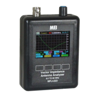
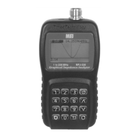
MFJ-223 Vector Impedance Antenna Analyzer
MFJ Enterprises, Inc
8 Version 1
and static discharge, high RF levels will also damage the
coupler. Never connect to a transceiver that could accidentally
transmit into the analyzer, and always check the interference
display when testing in high-RF areas. Disconnect immediately
if high pickup is indicated.
Important Protection Warning: Never connect a DC voltage
or static-charged coaxial line to the analyzer.
3.0 DDS Frequency Entry
3.1 Tuning:
The MFJ-223 tunes continuously from 0.5 to 60
MHz with a choice of five tuning rates. All selection is done
using the Encoder and Encoder Switch:
Rotary Encoder: Rotate the encoder knob to change frequency.
Each encoder indent shifts frequency by one tuning increment.
Use smaller increments for in-band tuning and larger
increments for rapid shifts or band changes.
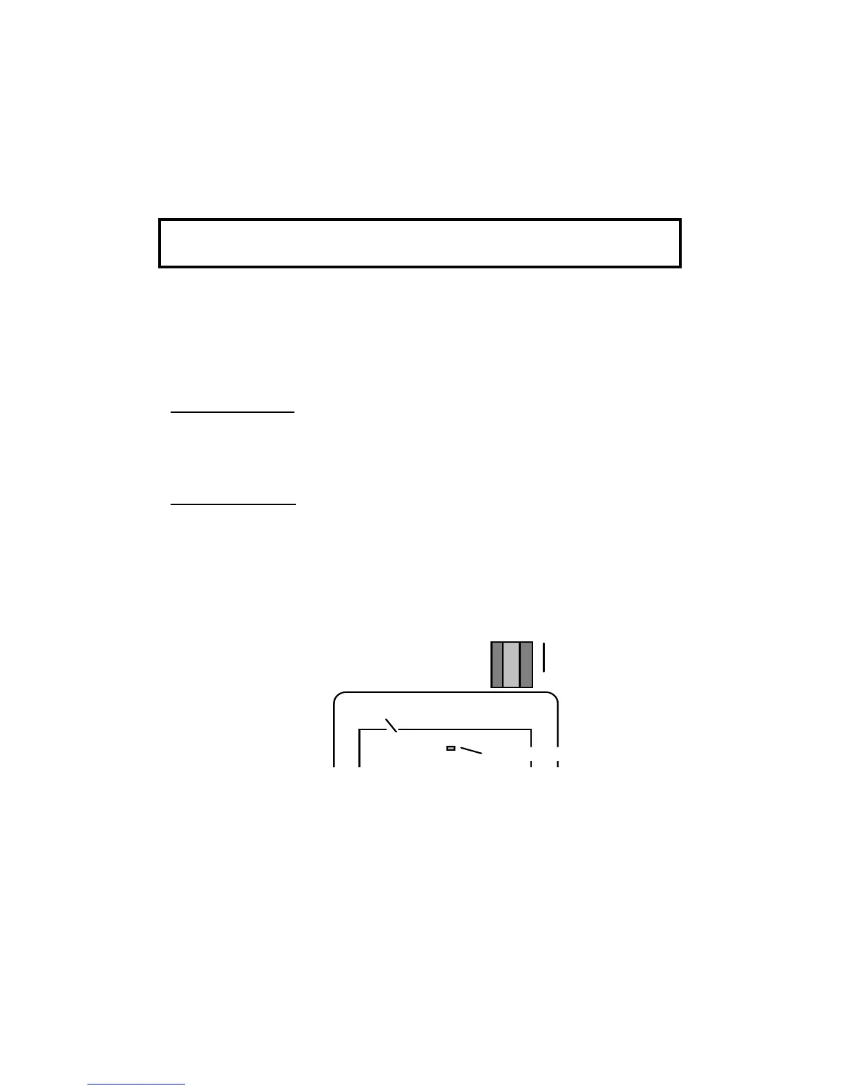
Encoder Switch: Depress the encoder switch to scroll through
the five available tuning rates. They are: 100-Hz, 1-kHz, 10-
kHz, 100-kHz, and 1-MHz. A highlighted placeholder appears
below the analyzer's digital frequency display to designate the
selected increment (see below).
3.2 Rounding Off the Display:
When you change the DDS
step size (or increment), the new step will be added to -- or
subtracted from -- the analyzer's current frequency setting. For
example, if the current frequency is 3.920 MHz and you select
a 1-MHz increment, rotating the encoder knob clockwise will
advance the frequency from 3.920 to 4.920 > 5.920 >
6.920...etc. in 1-MHz hops. As an alternative, you may choose
Fre 14.2500MHz
Step-Size Placeholder
V
Press to scroll
Step-Size
Rotate to
Change
Frequency
DDS Frequency Readout