Do you have a question about the MFJ 226 and is the answer not in the manual?
Describes the analyzer's two main operational modes for testing.
Details calibration procedures and device settings for optimal use.
Explains how to connect the analyzer to a PC for data management.
Covers frequency range, resolution, output power, and harmonics.
Details the LCD display, physical size, weight, and power needs.
Specifies the USB interface and OSL calibration compatibility.
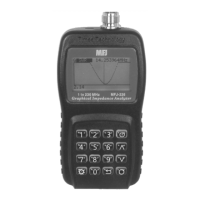
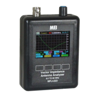
Describes the test port, USB port, and the device's LCD screen.
Explains the function of all buttons for device operation.
Details the location and access method for the battery compartment.
Instructions on using AA batteries to power the device.
Outlines the main menu and its five primary sub-menus.
Guide to accessing and navigating the device's settings menu.
Settings for screen illumination and automatic shutdown.
Options for battery indicators and LCD contrast adjustment.
Settings for data security and viewing system details.
Steps to enter the mode and configure the test frequency.
Describes the SWR, Z, R, and X data screens.
Explains screens showing series and parallel impedance values.
Details rectangular and polar S11 representations of the load.
How to enter the mode and understand the screen layout.
Setting start and stop frequencies for frequency sweeps.
Adjusting plot scale and understanding calibration's role.
Explains the Open/Short/Load calibration concept for accuracy.
Details managing global calibration data for the analyzer.
Steps for creating and saving local calibration data.
Steps for performing the global calibration procedure.
How to save measurement data to files for later use.
Using grid lines and recalling saved measurement data.
Explains SWR, Impedance Magnitude (Z), and Resistance (R) screens.
Details Reactance, Return Loss (S11), and Phase Angle screens.
Explains the use and interpretation of the Smith Chart.
Information on required calibration loads for accuracy.
Using the PC host program for analyzer control and data acquisition.
Direct serial port commands for data capture and control routines.
Step-by-step guide for updating the device firmware via USB.
Details the product's warranty coverage, limitations, and claims process.
The MFJ-226 is a compact, single-port Vector Network Analyzer (VNA) designed for characterizing complex RF loads in 50-Ohm systems with high accuracy. It is part of the Times Technology Series of analyzers and is packaged for portable use, offering advanced features typically found in more expensive units.
The MFJ-226 functions as a graphical antenna impedance analyzer, capable of measuring and displaying various RF parameters. It operates by generating a test signal through a directional coupler to the load under test. Any impedance mismatch causes a portion of the signal to be reflected back. The directional coupler measures the amplitude and phase of both forward and reflected signals, feeding this data to a microprocessor. The microprocessor then converts this data into useful engineering parameters such as SWR, complex impedance, and S11 coordinates, which are displayed on the LCD screen.
The analyzer supports two primary operating modes:
| Brand | MFJ |
|---|---|
| Model | 226 |
| Category | Measuring Instruments |
| Language | English |