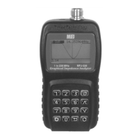
MFJ-226 Graphical Antenna Impedance Analyzer
5 Version 1A 1R02
1 2 3
4 5 6
7
8
9
0
MFJ-226
1
2
3
4
5
7
8
10
6
9
LAYOUT AND CONTROLS
1. Analyzer Test Port: N-Female, accepts N-male for DUTs and
calibration loads.
2. USB Data Port: Accepts micro-USB connector, interface
with a PC for download. (Not for powering
the unit or charging batteries).
3. LCD Screen: Displays menu selections, plots, and test
data.
4. Boot Key: Boot key, press and hold to turn analyzer
on or off.
5. Arrows (up/down): Step or scroll for menu selections and
frequency tuning.
6. Enter Key: Enters menu selections and frequency
setups.
7. Return (Exit): Escapes from current function, returns to
previous function.
8. Mode: Sets decimal point for numerical entries,
serves multiple menu functions.
9. Battery Door: Located on back, accesses tray holding
two AA cells.
10. Numerical Keypad: 0-9 keys for entering frequencies or
numerical data.