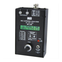
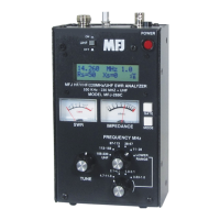
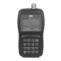
MFJ-226 Graphical Antenna Impedance Analyzer
10 Version 1A 1R02
ENTERING SWEPT FREQUENCY MODE
This mode plots seven test parameters over a frequency span of your
choice. Local Calibration may be used in this mode for accuracy
through transmission line.
Standing Wave Ratio (SWR)
Impedance Magnitude (Z)
Resistance (R)
Reactance (-X or +X)
Return Loss (RL)
Phase Angle (Deg)
Smith Chart
To select a display choice in the Sweep-Freq Menu, use the Up/Down
Arrow keys to make a choice and press Enter. Use the Return Arrow
to revert back to the Menu.
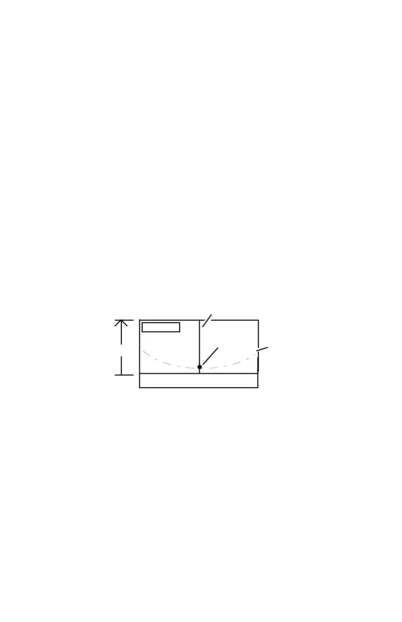
General Screen Layout: The LCD layout for all modes except the
Smith Chart is shown below. A tunable marker is available for all
screens and presents precise numerical data to describe any point
you select along the X axis of the plot.
Tunable Marker
Plot
Numerical Data Window
Data
Numerical
Data
Function
Frequency
SWEPT-FREQUENCY SETUP
Swept-Freq operations require some initial setup using prompts
controlled by the Mode key. These prompts will appear in the
numerical data window at the bottom of the LCD screen. Entry items
include:
Start Frequency: At the prompt, use the keypad or scroll-step
procedure to create a start frequency for your sweep. The Mode key
sets the decimal point and Enter applies your selection.
Stop Frequency: Same as above -- enter the sweep stop frequency.


 To Next Page