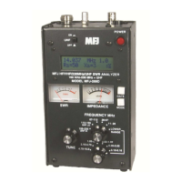
MFJ-226 Graphical Antenna Impedance Analyzer
15 Version 1A 1R02
include measurements taken at as many frequencies as possible.
The Microprocessor and DDS handle the "resolution" task
automatically. Calibration will be only as good as the load set used.
Poorly made loads will add errors to the calibration causing the unit to
loose accuracy especially in the VHF range.
High RF Fields may interfere with antenna measurements. You can
check the accuracy with known loads to verify that the MFJ-226 is still
calibrated.
Global Calibration File
All of the MFJ-226 analyzer’s calibration data is stored in flash
memory. Five cal-memory slots are available. One contains the
Global calibration file. The Global file covers the entire 1-MHz to 230-
MHz frequency span. Normally, the Global Cal establishes the
reference plane at the analyzer’s N connector. By default, the Global
Cal applies to all Single-Frequency measurements. It also applies to
Swept-Frequency measurements unless you preempt it by loading in
a Local-Cal file from one of the four remaining memory slots. The
letter “G” may appear in the upper-left corner of the LCD screen when
Global Cal is applied. The letter L appears in the upper left corner of
the LCD screen when Local Cal data is used.
Building a Local Calibration File
Local calibration is normally used for measuring loads through a
transmission line when you do not want to introduce the cable’s loss
or phase shift into your data. To perform the Local Cal, you will
connect the OSL loads out at the far end of the cable. During the
Local Cal procedure, the analyzer compensates out losses and phase
shift in the cable and thereby shifts its reference plane out to the load.
Memory slots numbered 1-4 are reserved for building and saving
Local Cal files. To build a file, use the entry procedure outlined below
and follow the on-screen prompts.
Press the Mode key until the Calibrate prompt appears
onscreen, then press Enter.
Select one of the four storage slots and press Enter. .
Note that calibration data and DDS frequencies are linked together in
a "data set". If you decide to alter the frequency range of your plot
after establishing a Local Cal set, the processor will recognize the
shift and automatically reject the Local Cal, reverting back to Global
Cal.. Likewise, if you save a Local Cal data set into memory and
reload it at a future time, the original DDS frequencies will
automatically be pulled up as part of the set.


 To Next Page