MFJ-226 Graphical Antenna Impedance Analyzer
14 Version 1A 1R02
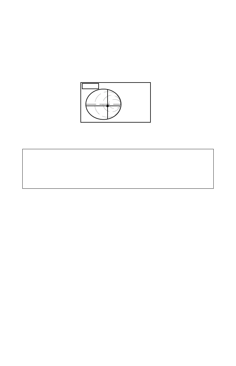
Smith Chart Screen: The Smith Chart is a very popular tool for
visualizing complex impedance relationships in transmission lines and
antenna systems as a function of frequency. Note that the Smith
Chart frequency marker is displayed as a cross-hair that follows the
load's impedance parameters in both the X and Y axis. Normalized
numerical data defining the marker position is displayed to the right-
hand side of the plot.
SMITH
14.015840 MHz
0.1793
-54.89
DEG
CALIBRATION
NOTE: DO NOT try to run the global CALIBRATE procedure without a
set of calibration loads. DO NOT UNLOCK the CAL DATA PROTECT
except during the Global CALIBRATE procedure.
The MFJ-226 is accurately calibrated at the factory and should not
need recalibration for initial use.
The MFJ-226 uses Open/Short/Load (or OSL) calibration to maintain
high accuracy for its Global Calibration -- and for "Local Calibration".
Local calibration is used in place of Global Calibration to eliminate
amplitude and phase errors in test cables or transmission line for
specific Swept-Frequency tests. The OSL calibrate procedure will be
familiar to many with RF-engineering backgrounds because it is the
industry standard procedure for setting up professional laboratory-
grade analyzers.
The OSL (Open/Short/Load) “load set” consists of three coaxial
terminations (typically built into connectors). One connector is a
calibrated OPEN (O) to represent an infinitely high impedance. The
second is a calibrated SHORT (S) to represent zero impedance. The
third is a precision (non-reactive) 50-ohm load (L) to represent 1:1
SWR. The analyzer measures all three loads at close frequency
intervals to establish the electronic calibration (or reference) plane of
the analyzer. The Cal Plane represents the point in a transmission
system where the analyzer encounters no intervening losses or
phase shift between the detector and the load being tested. Because
phase shift and loss both change with frequency when traveling
through transmission line, the analyzer’s calibration data set must
 Loading...