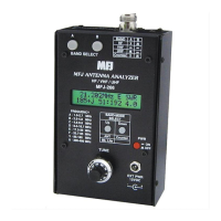
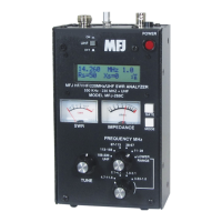
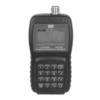
MFJ-226 Graphical Antenna Impedance Analyzer
9 Version 1A 1R02
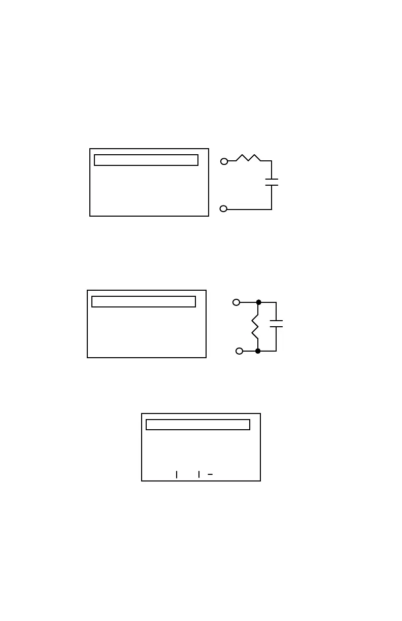
Screen 3, Series Impedance: Displays the load's resistive and
reactive component as two discrete elements connected in series.
Also displays a true reactance sign and the inductive or capacitive
value at the test frequency. This screen can also be used to
determine the value of a capacitor in pF or inductor in mH at the
operating frequency.
IMPEDANCE
FREQ: 223.500 MHz
101.80 - j112.58
3.25pF
SERIES
101.8
3.25pF
Screen 4, Parallel Impedance: Displays the resistive and reactive
components as two parallel elements. Also displays true reactance
plus a finite inductive or capacitive value.
IMPEDANCE
FREQ: 223.500 MHz
240.10 - j194.53
1.88pF
PARALLEL
240.1
1.88pF
Screen 5, S11 Scattering Parameters: Displays Rectangular and
Polar S11 representations of the load.
S11
FREQ: 223.500 MHz
RECTANGULAR:
0.58 + j0.34
0.67 < 30.10
POLAR:
For all screens, press the Return Arrow to return to the Main Menu.


 To Next Page