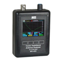
MFJ-223 Vector Impedance Antenna Analyzer
MFJ Enterprises, Inc
16 Version 1
6.3 Coupler Loss and Directivity:
Simple broadband
couplers of the type used in the MFJ-223 may exhibit accuracy
limitations, especially at the higher end of the analyzer's
frequency range. Although accurate enough for amateur radio
applications, they typically lack the high degree of precision
and linearity needed for testing antennas and RF devices to
commercial or laboratory standards.
6.4 Calibration Plane Error:
The Calibration Plane is the
point of reference where all measurements have the greatest
accuracy (Gain Reference = 0dB and Phase Shift = 0 degrees).
For a basic handheld like the MFJ-223, the calibration plane is
fixed at the RF connector. Any time a transmission line is
installed, it displaces the load from the calibration plane and
introduces error. For SWR readings, the error is mainly caused
by loss in the cable (more loss means greater the error).
Generally, this condition isn't a problem because your radio
and the analyzer both see the same reduction in SWR.
However, if you're documenting antenna-SWR for design
purposes, the analyzer should be connected directly to the
feedpoint through a short pigtail to minimize error.
Calibration-plane error has far more significance for measuring
impedance because of phase rotation in the cable. In fact,
impedance readings may swing dramatically, depending on the
cable's electrical length and the severity of the load's mismatch
referenced to 50 Ohms. For meaningful impedance data,
always connect the analyzer directly to the DUT using the
shortest cable possible.
6.5 Reactance Sign Ambiguity:
Most handheld analyzers,
including the MFJ-223, lack the processing capability to directly
calculate the reactance sign for complex impedance (Z = Rs
±j).