MFJ-223 Vector Impedance Antenna Analyzer
MFJ Enterprises, Inc
4 Version 1
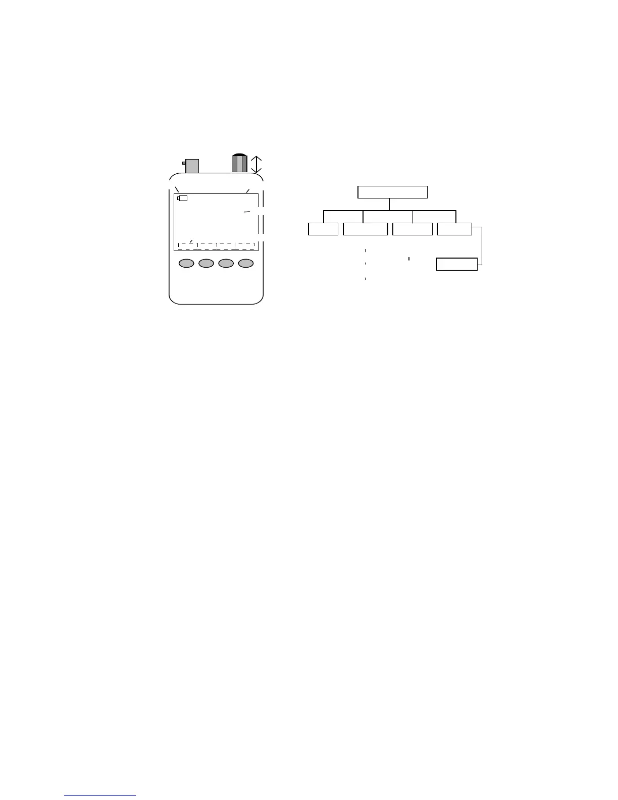
1.3 Layout and Controls
00:20:08
Help System Single
Scan
90
MFJ K5MFJ
Vector Impedance Analyzer
BAND: 0.5-60 MHz
1. RF Connector
2. Rotary Encoder
4. Battery Status
5. Elapsed Time
6. Personalized ID
7. Soft-key Switch Labels
3. Control Switch
8. Membrane Control
Switches
Boot Screen
Help
System
Single
Scan
Present
(8-Pages)
Help
Files
Enter
Call
Auto-Off
Enable
Battery
DVM
Boot
Counter
Single
Frequency
VNA
Set Up
Scanned
Plots
View
Scanned
Plots
Signal
Gen
1. RF Connector: BNC-female. Use any SO-239-to-Male BNC
adapter when testing with PL-259 connectors (MFJ-7708 or
equivalent).
2. Rotary Encoder: Tunes DDS frequency when setting up
tests, positions marker when reviewing plot data, and scrolls for
some system set-up functions.
3. Encoder Control Switch: Turns unit on and off, selects
tuning steps, and scrolls through some setup menu choices.
When used for power-off function, the Boot Screen must be
displayed.
4. Battery Status: Indicates battery power remaining, warns
when the battery is running low.
5. Elapsed Time: Displays running time for the current
operating session.
6. Personalized ID: Displays owner's call letters or name (see
Chapter 2.4 for entry instructions).
7. Soft-Key Switch Labels: Displays the analyzer command-
key assignments (key assignments change for different
operating modes).
8. Membrane Control Switches: Enters command instructions
into the analyzer's processor.