AUTOMATION TESTING AND COMMISSIONING
––– STEP 8 –––
SETTING THE ELECTRICAL LINE
FOR PERMANENT POWER SUPPLY
After programming, before testing and commissioning the automation, it
must be permanently connected to the mains by means of a special pow-
er line equipped with a disconnect device.
8.1 - CONNECTING THE AUTOMATION PERMANENTLY
TO THE POWER MAINS
CAUTION! – Incorrect connections can cause faults or hazardous
situations; therefore strictly observe all connections specified in this
paragraph.
8.1.1 - Replacement of the power cable
01.Remove the power supply unit
To perform this operation, read the instructions in paragraph A.2
(chapter “Further details”), but only disconnecting the wires phase
and neutral (there is no need to disconnect the earth wire or connec-
tor with the 5-cable plate).
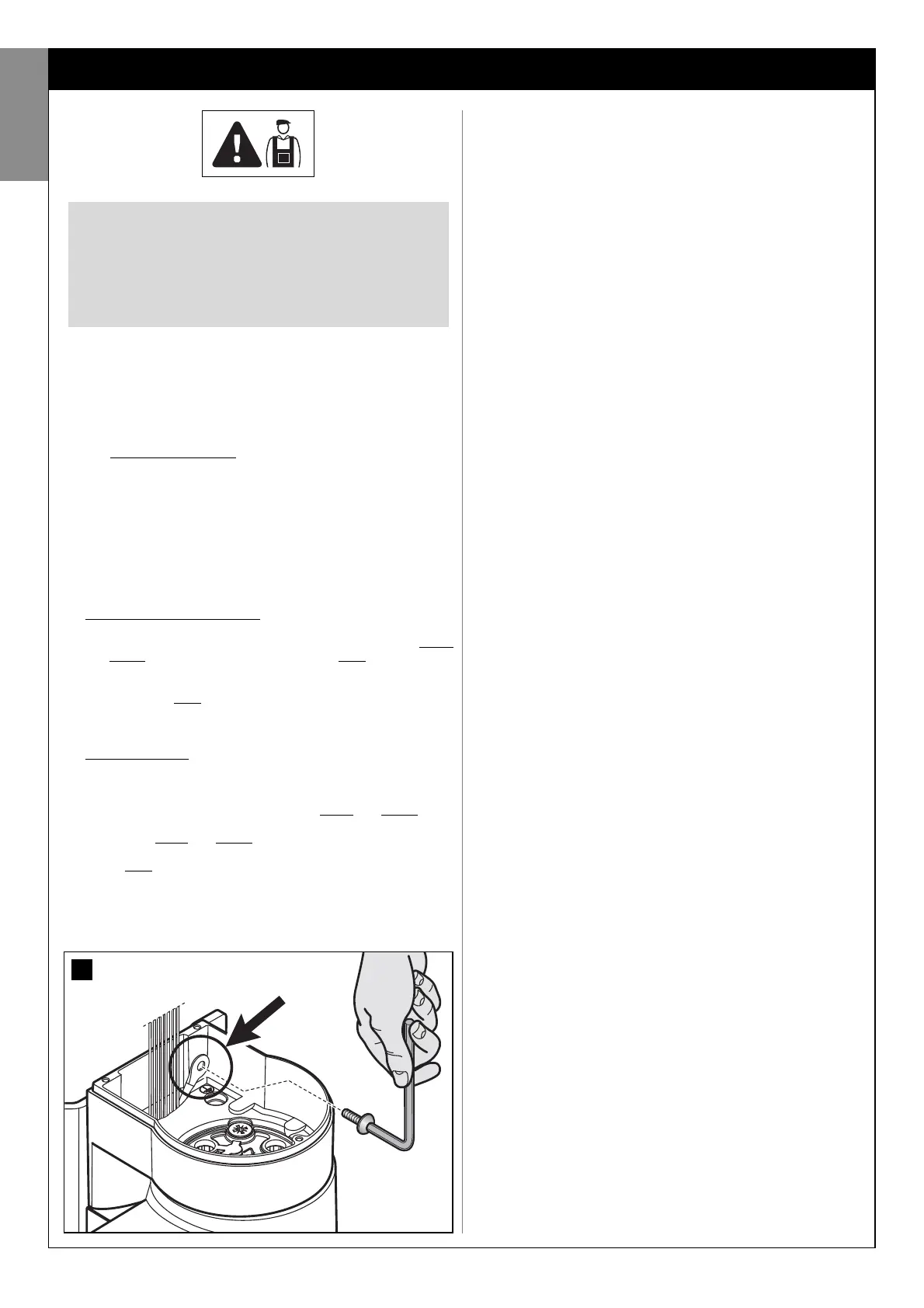
02.In the area housing the power supply unit, remove the screw securing
the eyelet of the earth wire (fig. 30).
03.Remove the control unit
To perform this operation, read the instructions in paragraph A.1
(chapter “Further details”).
04.Replace the cable
Loosen the cable clamp screws; withdraw the power cable (supplied
as standard) and insert the new cable (for cable specifications, refer
to paragraph 3.3.4).
05.Strip the cable to approx. 80 mm, and the phase and neutral wires,
after which insert the sheath taken from the previous power cable.
06.Connect the phase and neutral wires to the power supply unit termi-
nal board, observing the specifications on the label.
07.On the earth wire, insert a crimp terminal without insulation, using a 6
mm eyelet.
08.In the area housing the power supply unit, use a screw to secure the
two eyelets for the earth wires (fig. 30 – Caution! - Direct the crimp
terminal towards the outlet of the power cable).
CAUTION! – All operations described in chapters 8,
9, 10 may constitute a hazard. Therefore they must
be performed exclusively by skilled and qualified
personnel, in observance of these instructions and
current safety standards applicable in the place of
use.
09.Slowly pull the power cable downwards until a sufficient cable length
is left to rotate and close the power supply unit.
10.Then, firmly position the seal in its seat and close the power supply
unit cover with all screws (caution! - A missing seal or screw may
cause problems with internal electronics).
11.Lastly, tighten down the screws of the cable clamp, insert the control
unit in its seat, refit the cable ducting support and refit the lower cov-
er of the gearmotor.
8.1.2 - Installing the safety devices on the electrical line
The automation power line must be equipped with a device for protection
against short circuits and a device for disconnection of the automation
from the power mains (neither devices are supplied with the kit).
The disconnect device must have contacts with a sufficient gap to ensure
complete disconnection, in compliance with the overvoltage category III,
according to the installation instructions.
If necessary, this device guarantees quick and safe disconnection from
the mains power and therefore must be positioned in sight of the automa-
tion. If located in a concealed position, it must be equipped with a system
that prevents inadvertent or unauthorised reconnection of power, to avoid
potential hazards.
––– STEP 9 –––
AUTOMATION TESTING
AND COMMISSIONING
Testing and commissioning of the system are the most important phases
in automation set-up, as they will guarantee maximum system safety. The
testing procedure described below may also be used to periodically
check the devices making up the automation.
Testing and commissioning of the entire system must be performed
by skilled and qualified personnel, who are responsible for the tests
required to verify the solutions adopted according to the risks pres-
ent, and for ensuring observance of all legal provisions, standards
and regulations and in particular all requirements of the standard EN
12445, which establishes the test methods for checking automations
for gates.
9.1 - TESTING
01.Ensure that all instructions and warnings in STEP 1 have been strictly
observed.
02.Using the selector or radio transmitter, test a gate closing and open-
ing cycle and ensure that the leaf movement corresponds to specifi-
cations. A number of tests should be performed to ensure that the
gate moves smoothly and that there are no assembly defects, incor-
rect settings, or any points of friction.
03.Ensure correct operation of all safety devices in the system (photo-
cells, sensitive edges, etc.), by activating them one at a time during an
opening and/or closing manoeuvre. In particular, each time a device is
activated, check on the control unit that the Led “ECSBus” emits a
longer flash; this confirms that the control unit has recognised the
event.
04.To test photocells and in particular that there is no interference with
other devices, pass a cylinder (diameter 5 cm, length 30 cm) through
the optic axis (fig. 31). Pass the cylinder first close to the TX photo-
cell, then close to the RX and lastly at the centre between the two.
Ensure that in all cases the device engages, changing from the active
status to alarm status and vice versa, and that the envisaged action is
generated in the control unit (for example movement inversion in the
Closing manoeuvre).
05.Measure the force as specified in the standard EN 12445. If the motor
force control is used as an auxiliary function for reduction of impact
force, test and identify the setting that obtains the best results.
9.2 - COMMISSIONING
Commissioning can only be performed after positive results of all test
phases. Partial or “makeshift” commissioning is strictly prohibited.
01.Produce the technical documentation of the automation, which must
include at least the following documents: the overall layout drawing
of the system (see example in fig. 4), the electrical wiring diagram
(see example in fig. 26), the analysis of risks present and relative
solutions adopted, and the manufacturer’s declaration of conformity
of all devices installed (use appendix 1).
02.Affix a dataplate on the gate, specifying at least the following data:
type of automation, name and address of manufacturer (responsible
30
English
22 – English