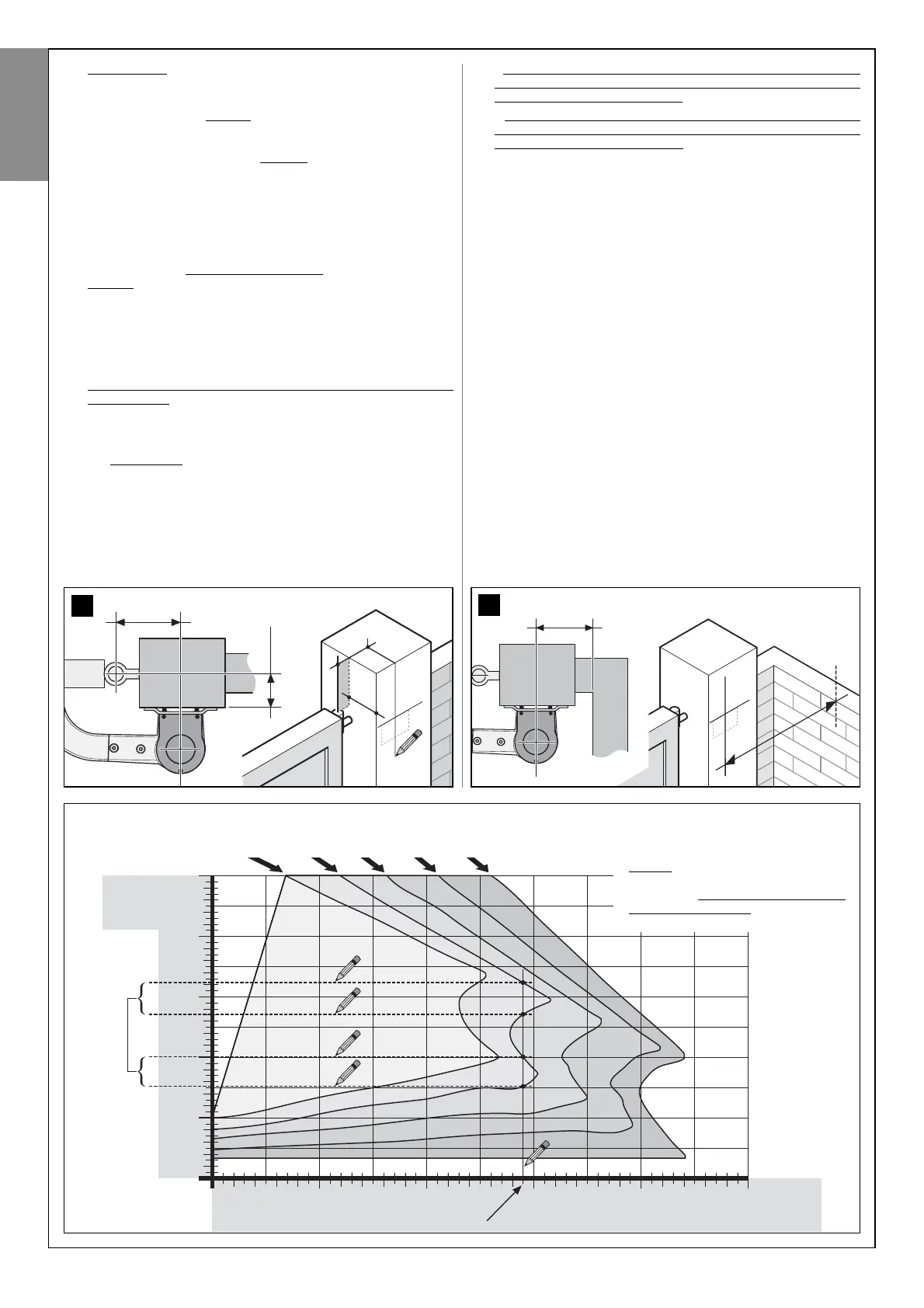
GRAPH 3 (see paragraph 3.4)
EXAMPLE: if a maximum opening
angle of 105° is required, and value B on
the gate post is measured at 145 mm,
value A can be selected from one of the
values from 125 to 150 mm or from 185
to 210 mm. In both cases, the minimum
value is recommended.
(compatible A values)
the gearmotor is to be positioned.
a) - On Graph 3 locate the line marked with the same maximum opening
angle as that measured.
b) - On the post, measure value B (fig. 11), i.e. the distance between the
fulcrum of leaf rotation (centre of the hinge pin) and the post surface
where the gearmotor is to be fixed.
c) - On Graph 3 note the obtained value B on the horizontal axis and
from this point, trace a vertical line until it intersects the line with your
maximum leaf opening angle (see example in graph).
d) - On Graph 3 trace a horizontal line passing through each point of
intersection created between the previously traced vertical line and
the line with your maximum leaf opening angle.
Then on the vertical axis, read all values of “A” including those
between the traced horizontal lines (see example in graph) and where
feasible select the minimum possible value. This will be the required
value A.
e) - On the post, note the selected value “A” and trace a vertical line from
this point (fig. 11). The line must intersect the horizontal line already
present; these two lines will serve as a reference for subsequent fix-
ture of the gearmotor.
f) - Lastly, release the gearmotor with reference to the chapter “Manually
locking and releasing the gearmotor”, in the “Operation Manual”.
05. Determining the procedure to be followed to complete gearmo-
tor installation.
a) - CAUTION, VERY IMPORTANT! At this point if there is a wall,
pole or other fixed element behind the post, to determine
whether this may obstruct complete rotation of the arm, meas-
ure distance E
(fig. 12), i.e. the space between the previously
traced vertical line on the post at the closest point of the obsta-
cle. Then,
- if
distance E is between 80 mm (minimum) and 299 mm (max-
imum), continue installation according to procedure 4.1B. (this
envisages shortening of the arm);
- if distance E is equal to or greater than 300 mm, continue
installation according to procedure 4.1A (this envisages the
standard arm length as supplied).