After considering points a, b, c, observe fig. 6 and on a piece of paper
draw a similar layout, adapting it to the specific needs of your systemThis
layout will serve as a guideline to dig the raceways for the cable ducting
and to make a complete list of the cables required.
3.3.4 - Selecting and sizing all connection cables
To select the type of cables and cut these to an adequate length, consult
Table 2; then, with the aid of the previously drawn layout (ref. paragraph
3.3.3), make on-site measurements to establish the length of each cable.
Caution! - No cable must exceed the specific maximum length stated in
Table 2.
Power cable
– The power cable on the WT1SC gearmotor serves to
make provisional connections
to the mains (for example, to perform pro-
gramming and the operation tests). Then, to test and start-up the
automation, it must be connected permanently to the mains, using the
specific cable stated in Table 2. This cable must be used on the system.
3.3.5 - Installation site preparation work
Prepare the area for subsequent installation of the devices, completing all
preliminary work, such as:
- digging of raceways for protection ducting of electric cables (external
ducting may be used as an alternative);
- laying of ducting and fixture in raceways;
- routing of cables through ducting. Caution! - In this phase, do not
make any electrical connections.
-Etc.
Warning:
•The hoses and ducting serve to protect electrical cables and prevent
accidental damage in the event of impact.
•Position the ends of the ducting at the points envisaged for fixture of the
various components.
•When laying pipelines, take into account the risk of possible deposits of
water in the branch wells, where condensate may form in the pipelines
and the control unit with possible damage to the electronic circuits.
3.4 - VERY IMPORTANT!
DETERMINING THE INSTALLATION PROCEDURE
TO FOLLOW (with standard arm or short arm)
IMPORTANT PREMISE – The gearmotor arm can be shortened
with respect to the standard length as supplied. A shorter
length may be required where there is a fixed obstacle (wall,
post, etc.) is located behind the post (where the gearmotor is
to be installed), preventing complete movement of the arm.
Therefore, before starting installation
the following procedure
should be performed to then decide whether to use procedure
4.1 and 4.2 (the latter requires shortening of the arm).
Warning – Incorrect installation may cause serious physical injury to
those working on or using the system.
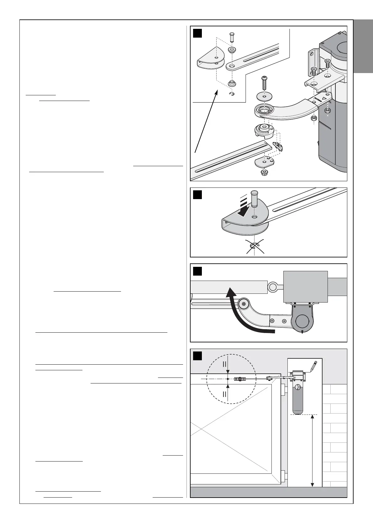
01. Assemble the components making up the gearmotor arm
.
a) - Refer to fig. 7, but without inserting the stop benzing (fig. 8); this will
be inserted later. Caution! - position the elbow fitting of the arm so
that is curved towards the leaf of the gate (fig. 9) when the gearmo-
tor is installed.
02. Establishing the height from the ground of the gearmotor when
installed on the post.
a) - Place the gearmotor on the post and position it so that the bracket
(fixing the arm to the leaf) is located on the upper section of the leaf,
in a sturdy zone, for example the load-bearing frame (fig. 10). If
another similarly strong area of the leaf is selected to fix the bracket of
the arm, it is important to ensure that the distance from the ground of
the lower section of the gearmotor is at least 40 cm.
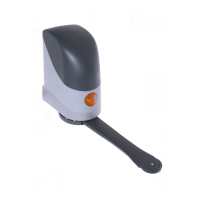
Warning – Never install the gearmotor upside down (see fig. 3).
b) - Keeping the gearmotor in this position, check that it is perfectly level,
and, using a pencil, trace a line on the post passing along the upper
edge of the bracket for fixing the gearmotor to the post. Then remove
the gearmotor.
03. Setting the required maximum leaf opening angle.
a) - Move the gate leaf to the required maximum opening position (with-
out exceeding 110°) and block with a stop on the ground, to secure
it provisionally in place. Caution! – To ensure correct system oper-
ation, mechanical stops must be mounted on the floor or wall at
the maximum leaf opening and closing points. These stops are
not supplied in the pack and are not part of the Mhouse product
range.
04. Calculate value “
A” (fig. 11), i.e. the horizontal distance between
the leaf hinge pin
and the point on the post where the vertical axis of
9
8
7
10
minimum 40 cm
English
English – 7