- 13 -
order information:
L55x
Modem:
L55 - 0-300 baud FSK modem
L55A - 0-600 baud FSK modem
L55B - 1200 baud FSK modem
Micro-Comm, Inc. • 15895 S Pflumm Rd • Olathe, KS 66062 • (913) 390-4500 • fax: (913) 390-4550 • www.micro-comm-inc.com
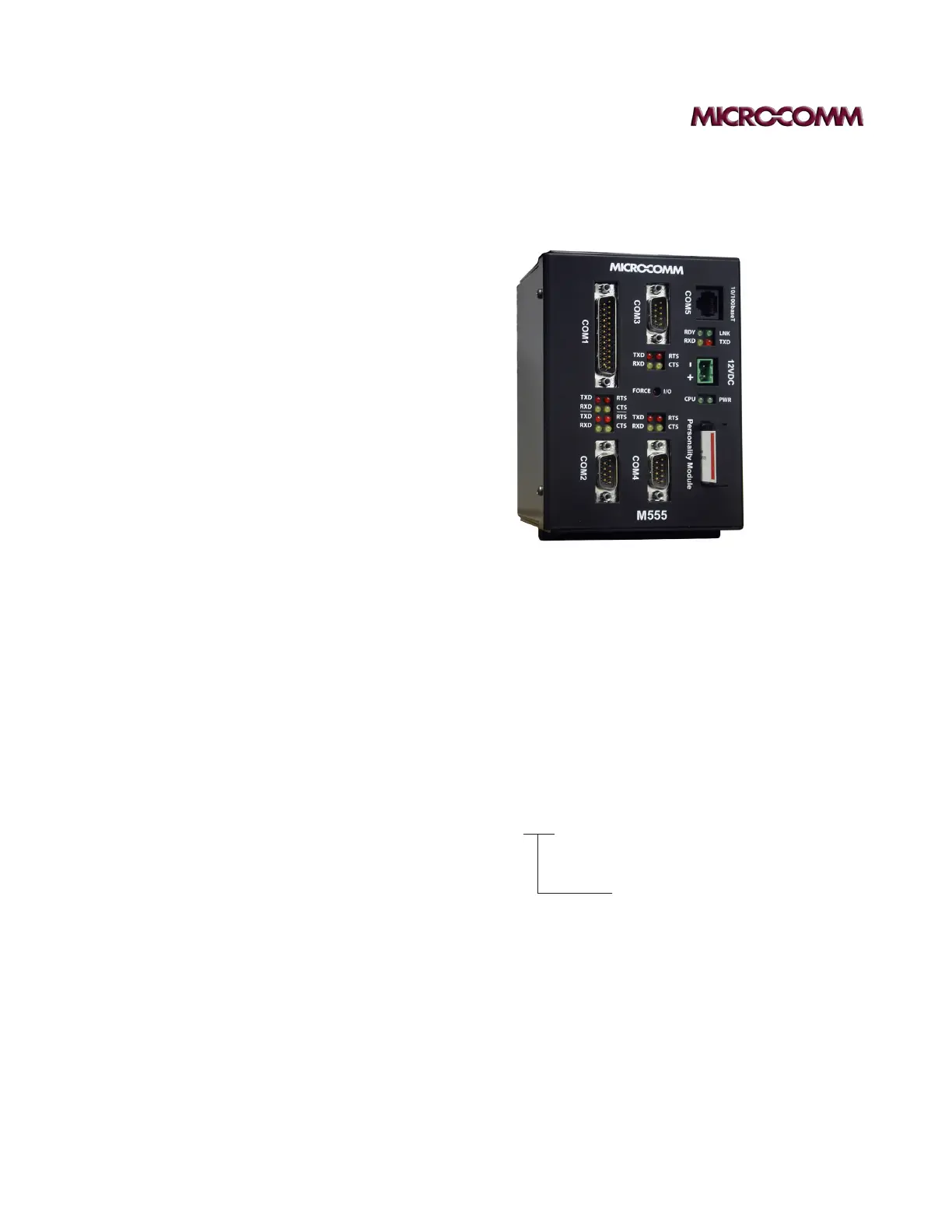
m555 plC
i/o
• 4 Open Collector Outputs, 100mA @ 12VDC (COM1 pins)
Internal clamping diode to 12V, Used only for antenna switching, not
field wire-able
• 2 On-Board Sensor Analog Inputs, 12bit, 0.1% accuracy
Box Temperature, 0-150°F
System Voltage, 0-25.5V
power sourCe and supplies
• Power Supply 12VDC Isolated Source with 8A Fuse,
Use 14AWG Supply Connections
• Power Input 10.5-15 VDC, 12VDC Nominal, 8.0A
• Quiescent Current 85mA
• COM1 (pins 9,10,11) 10.5-15VDC, 4.0A, Self Resetting Fuse
• COM2 (pin 4) 10.5-15VDC, 2.0A, Self Resetting Fuse
• COM3 (pin 4) 10.5-15VDC, 2.0A, Self Resetting Fuse
• COM4 (pin 4) 10.5-15VDC, 2.0A, Self Resetting Fuse
• The sum of the load currents must be 7.5A or less
• Temperature Range -40 to 50 degC (-40 to 122 degF)
Surrounding Air Temperature
• Internal Battery Lithium 3V, 1200mAh, 2/3A Size
(Real-Time Clock and NVRAM)
• Field Wiring - Use Copper Conductors Only, 60°C
Wire Range, 12-26 AWG
Wire Strip Length, 0.310”
Recommended Tightening Torque, 0.79 N-m / 7.0 lb-in.
Cpu and memory
• 32-bit MCU running 25MHz
• 1MB FLASH, Application Program
• 1MB RAM, Data
• 9MB Serial FLASH, Configuration
CommuniCations
• COM1, Radio Port
DB25M, RS-232 and RF signals
• COM2, Front Panel Display, Programming
DB9M RS-232 w/flow control lines
• COM3, RS-232/RS-485, DB9M
• COM4, RS-232/RS-485, DB9M
• COM5, Ethernet, 100Base-TX, RJ-45
• Plug In RF MODEM
FSK 0-300, 600, or 1200 BAUD
dimensions
• Height 6.45”
• Width 4.10”
• Depth 4.80” (with personality module)
• Weight 1.25 lb