- 28 -
Expansion I/O Module Setup
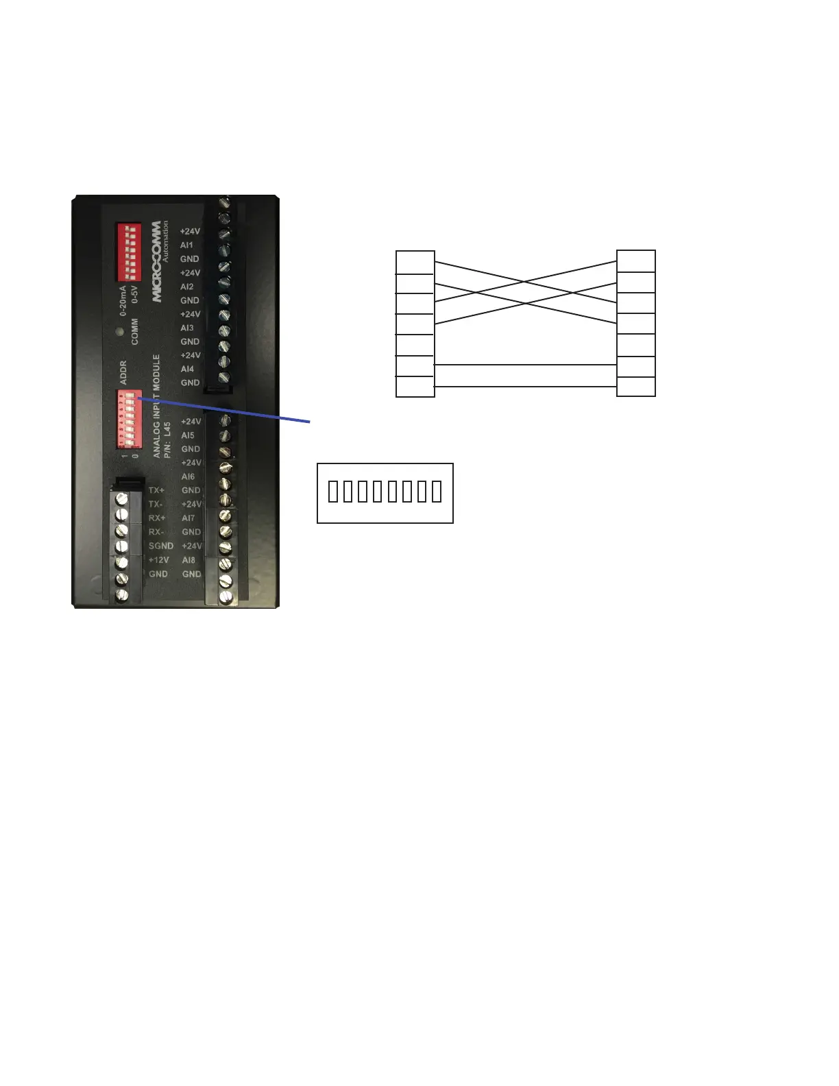
Dip switches set both the address of the module and the baud rate
used by the RS-485 connection to the RTU.
The EDI16, EDO16, EDO6R, EAI8 and EAO4 modules allow an
RTU to have additional discrete or analog inputs/outputs. These
modules are normally connected to the RTU using the COM3
terminal block or 9-pin port. Both power and communication lines
are provided by the RTU.
1 2 3 4 5 6 7 8
ON
TX+
TX-
RX+
RX-
SGND
+12V
GND
RTU (Master)
TX+
TX-
RX+
RX-
SGND
+12V
GND
I/O Module
Switches 1-7 set the address:
Module #1 = switches 1-7 off
Module #2 = switch 1 on, 2-7 off
etc.
The baud rate is set using switch 8:
9600 baud = switch 8 off
19200 baud = switch 8 on
The default baud rate used by the RTU is 9600 baud. This can be changed in the RTU Conguration 32
program if necessary. The normal COM3 Mirco-Comm I/O polling loop will take around 2.6 seconds to
update all modules at 9600 or around 0.7 seconds at 19200 baud. Micro-Comm I/O protocol on COM3
currently supports (4) EDI16, (4) EDO16, (4) EAO4 and (2) EAI8 modules.
All modules use Modbus RTU protocol and will be communicated with automatically using the “Micro-
Comm I/O” protocol or can be communicated with manually using the MESSAGE() or MIOMSG()
functions in script.
Note:
The Micro-Comm I/O polling loop was originally designed to extend the on-board physical I/O of an
S4500. It starts with locations that are outside the range of the S4500 on-board I/O: writing DO17-DO80,
AO1-AO16 and reading DI17-DI80, AI17-AI32.
(EAI8 Module)