- 5 -
i/o
• 8 Form C Relay Outputs, 5A @ 250VAC
• 8 Open Collector Outputs, 100mA @ 12VDC
• 16 Optically Isolated Discrete Inputs, Dry
Contact or Pulse Inputs
• 2 Optically Isolated High Speed Pulse Inputs
• 1 Pulse Amplification Circuit for Direct
Connection to Flow Meter
• 12 Analog Inputs
8ch, 12bit, 0-5V or 0-20mA
4ch, 12bit, 0-5V
• 1 Analog Amplifier Circuit
• 4 Additional On-Board Sensor Analog Inputs
Box Temperature, -50 to 150°C
Battery Current, ±10A
System Voltage
Receive Signal Strength
Power source and suPPlies
• 120/240 VAC Power Input isolation
transformer and surge suppression
• SOLAR charging circuit
• Battery charging and backup circuit
• 13.8VDC @ 8A Switching Power supply
• 12 to 24VDC @ 200mA
Sensor Excitation power supply
cPu and memory
• 32bit MCU running @ 16MHz
• 1MB FLASH EPROM, Application Program
• 512K RAM, Data
• 1MB Serial FLASH, Configuration
communications
• COM-1A, Radio Port
25pin Sub-D Male, RS-232 and RF signals
• COM-1B, Radio Monitor Port
9pin Sub-D Male TxD, RxD, RTS, GND
• COM-2, Front Panel Display
9pin Sub-D Male RS-232 w/flow control lines
• COM-3, RS-485, 1200–9600 BAUD remote I/O
• Plug In RF MODEM
0-300, 600, 1200 BAUD
order information
L15F-xxxx
Modem:
0 - none (110-19200 baud RS-232)
L17 - 0-300 baud radio modem
L17A - 0-600 baud radio modem
Micro-Comm, Inc. • 15895 S Pflumm Rd • Olathe, KS 66062 • (913) 390-4500 • fax: (913) 390-4550 • www.micro-comm-inc.com
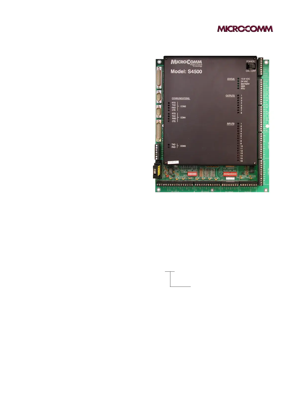
s4500 Plc
L15F-L17A