Just like a bar or horseshoe magnet, the
magnets supplied have one side
that is the north pole and
one side that is the south
pole.
13
Magnets
The number of magnets that must be used depends on
where you mount the sensor. On tractor or implement
wheels the general rule of thumb is one magnet for each
wheel bolt (minimum of two, and always an even number).
For drive shafts or small wheels (ATV’s), a minimum of
two magnets are required. Always use an even number of
magnets, and always alternate the polarities of the magnets.
Please read the following information about magnet spacing
and polarity.
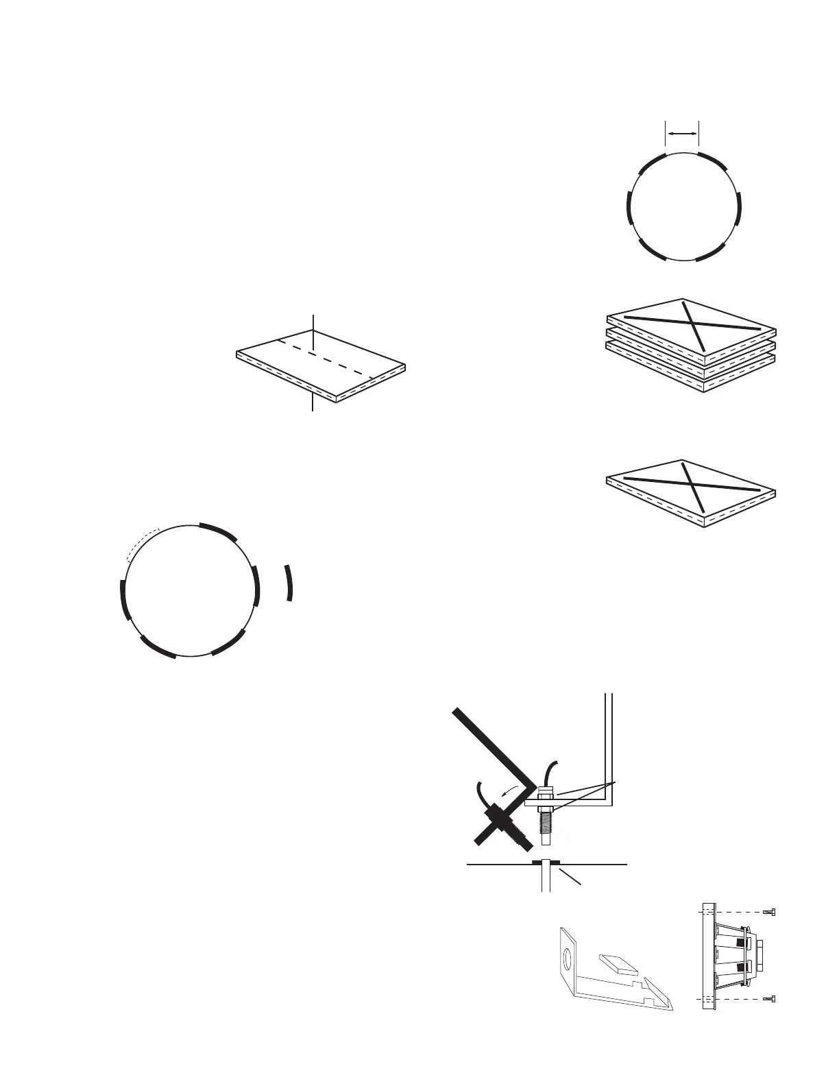
For proper operation, magnets must
be evenly spaced around the wheel
or drive shaft. Magnets must be at
least 1” apart.
On all installations, use an even number of magnets and
alternate polarities as you go around the wheel hub or drive
shaft.
Here’s an easy way to
make sure that you use the
correct side of each magnet.
Stick magnets together in
a stack. Put an “x” on the
top magnet. Remove that
magnet and put an “x” on
the next magnet. Continue until all magnets are marked.
Install magnets as shown below.
Mount the first magnet with
the “x” facing toward the
hub or shaft (IN). Mount the
second magnet with the “x”
facing away from the hub
or shaft (OUT). Continue until all magnets are mounted,
alternating polarities as you go around hub or shaft.
1” Minimum
N
North
North
North
South
South
South
1
2
4
3
5
6
Test magnet
should alternately
attract and repel.
Installation (cont)
Speed Sensor Installation (cont)
MagnetDrill lug
bolt hole and
bend
to fit hub.
Attaching Magnets to Hub
The magnets are attached to a wheel hub or drive shaft
and the speed sensor is mounted directly over the magnet.
When the wheel or drive shaft begins turning, a speed
impulse is sent to the MT-2400 console every time a magnet
passes by the tip of the speed sensor. For the speed sensor
to operate properly, the spacing between the magnets and
the tip of the sensor must always remain constant. Before
permanently mounting any parts, be sure that the location
you have selected will meet the following requirements
See Illustration 4.
NOTE: Observe magnet polarities (See Previous Page).
Refer to the following diagrams on the next page for
specific mounting instructions. Magnets may be attached
mechanically as shown or adhered with epoxy or other high
quality adhesive. When using adhesive, thoroughly clean
the area of dirt and oil. With either method of attachment,
wrapping the magnets with a layer of electrical tape is
recommended to provide additional protection from field
debris.
Illustration 4
45° max
Sensor
(Green body)
Magnet
3/8” nuts
Bracket must
be rigidly
mounted
Sensor assembly must not
be mounted more than
45° from perpendicular
¼” to ½” air gap
Illustration 5
 Loading...


