25
The run/hold sensor cable has a BLACK body and a GRAY tie
near the 3-pin M/P connector and mates with the main har-
ness ca ble having a GRAY cable tie near the 3-pin M/P con-
nec tor. Make certain that you install the correct sen sor cable
and connect it to the correct connector on the main harness.
See Illustration 30. If not using Run/Hold cable for remote
use, make certain a dust cover with jumper is installed.
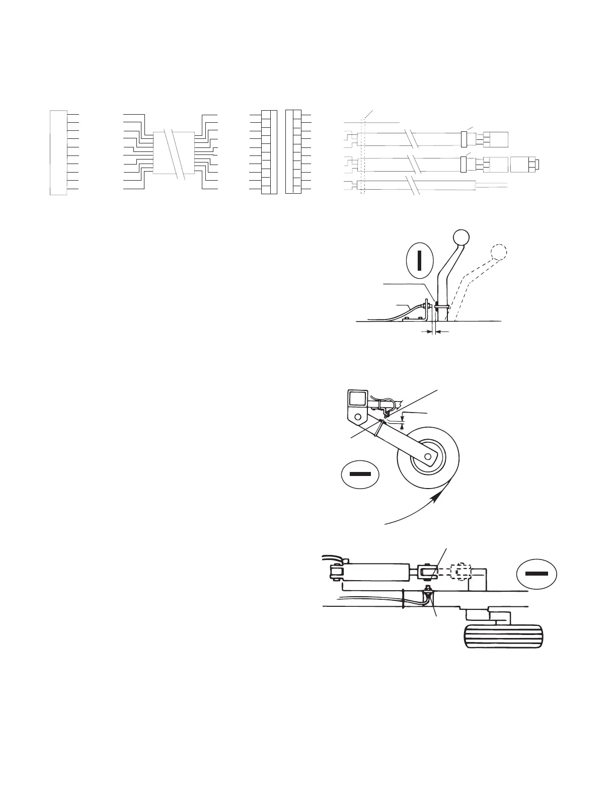
• The basic idea is to attach a magnet to a lever or some
part of the equipment that moves when the im ple ment
is raised and lowered. The Hall-effect Run/Hold sensor
is sensitive ONLY to the south pole of the magnet.
Check the polarity of the magnet by bring ing it near the
Run/Hold sensor with the console turned on. Note and
mark the face of the magnet that is toward the sensor
when the console does not indicate “HOLD.” Install the
magnet with the marked side facing the sensor. When
the mag net is away from the sen sor, the con sole will be
in HOLD and the area and distance counting functions
will be disabled. The solenoid valves will also shut off if
the optional relay kit has been installed. See page 47 for
details. NOTE: The run/hold kit includes a 5’ sensor cable
and 10’ extension. You may re quire additional extension
cables which are avail able in 5 ft. (1.5 m), 10 ft. (3 m), 15
ft. (4.5 m), 20 ft. (6 m) and 25 ft. (7.6 m) lengths.
• You may also use a toggle or other type switch. Sim ply
cut the blue jumper wire in the dust cover and splice on
an appropriate length of wire to reach your switch. Do
not connect to a switch with “live” power.
When switch is closed, console is in RUN. When the switch is
open, the console is in HOLD.
Installation (cont)
Remote Run/Hold
Illustration 30
LIFT WHEEL MOUNTING
ROCKSHAFT CONTROL LEVER MOUNTING
1/8” to 3/8 “ (6 mm to 13 mm)
space when equipment is
down and operating
Sensor Cable
(black body)
Magnet
South
North
Run Position
Hold
Position
1/8” to 3/8”
(6 mm to 13 mm)
when wheels are up
Magnet
South
North
Run
Position
Hold
Position
Sensor
(Black body)
Magnet
North
South
A
B
C
D
E
F
G
H
J
K
10-PIN METRI-PACK SHROUD
A
B
C
SPEED
RUN/HOLD
POWER
3-PIN
M/P 150
SHROUD
MT-2400 CONSOLE
OPTION
RELIEF CONTROL
SPEED POWER
SPEED SIGNAL
SPEED GROUND
RUN/HOLD PWR
RUN/HOLD SIG
RUN/HOLD GND
BATTERY GND
BATTERY PWR
20-GA. BRN
20-GA. RED
20-GA. ORN
20-GA. YEL
20-GA. GRN
20-GA. BLU
20-GA. VIO
20-GA. GRY
20-GA. WHT
20-GA. BLK
N/C
18-GA. RED
18-GA.WHT.
18-GA. RED
18-GA. BLK.
18-GA. WHT
18-GA. RED
18-GA. BLK.
18-GA. BLK.
18-GA. RED
A
B
C
D
E
F
G
H
J
K
10-PIN METRI-PACK TOWER
BLACK TIE
YELLOW TIE
RELIEF RELAY
GRAY TIE
3-PIN
M/P 150
TOWER
3-PIN
M/P 150
TOWER
A
B
C
A
B
C
 Loading...


