37
CONSOLE
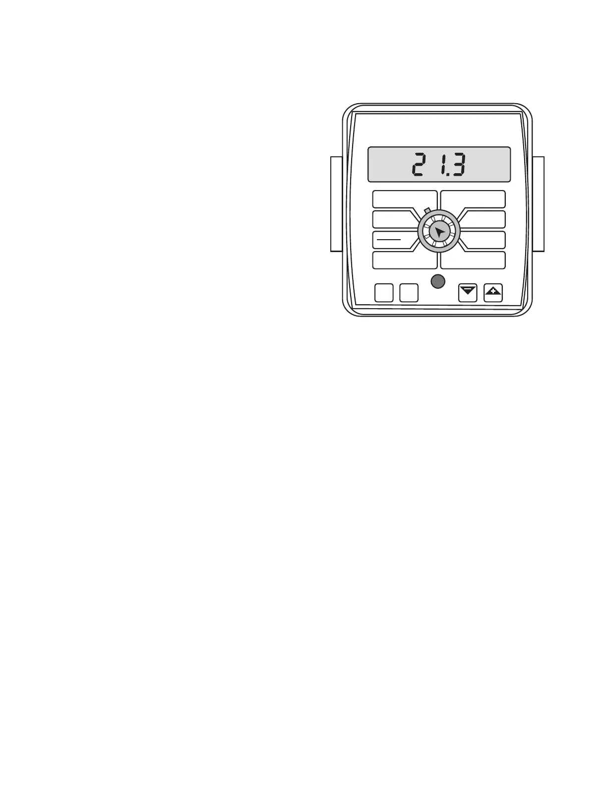
The MT-2400 control panel features a large, easy-to-read
back-lit liquid crystal display, exclusive BriteKnob
™
dial and
back-lit panel for night operation.
POWER SWITCH
Power should be connected to a switched 12-Volt power
source. Install an in-line fuse on unprotected circuits.
RUN/HOLD SWITCH
This system does not have a dedicated run/hold switch.
However, by adding the optional remote run/hold kit and
the run/hold relay kit, boom valves will automatically turn
ON and OFF as the run/hold sensor status changes. (Boom
switches and the Master switch remain in the ON position.)
BOOM SWITCHES
The system monitors the status of the boom control switches
to determine whether they are ON or OFF. The console
accumulates area based on the calibrated boom widths.
When an individual boom is turned OFF, the respective width
is subtracted from the total width to accumulate area based
on the new active application width. The numbers 1, 2, 3 and
4 on the display will light when their respective boom is ON.
AUTO/MAN BUTTON
This button will switch the control status of the system from
fully automatic to manual control. Each press of the button
will change the status. The display will show “AUTO” when
automatic control mode is active and “MAN” when manual
control mode is active.
CAL BUTTON
This button allows you to enter and exit calibration mode.
Pressing and holding the CAL button for approximately
three seconds will put the console in calibration mode. The
display will read “CAL” and the RED warning light will be
illuminated. Pressing and holding the CAL button again for
approximately three seconds will exit calibration mode and
return the console to normal operating mode. The display
will no longer read “CAL” and the RED warning light will turn
OFF.
Turn rotary dial to display desired readout
Operation
Console Switches and Buttons
Illustration 42
WIDTH
CIRC
MIN
FLOW
FLOW
CAL
AREA
HOUR
APP. RATE
TOTAL AREA
SPEED
DISTANCE
FLOW
RATE
TOTAL FLOW
SUB AREA
BOOM
SEL
TEST
SPEED
ADJUST
RATE
TARGET
RATE
AUTO
MAN
CAL
RESET
MANAUTO
HOLD
MT-2400
™
LR
V 1
2
3 4
“+” AND “” BUTTONS
These buttons are used to enter and adjust calibration values
when calibrating the system. During normal operation, when
automatic “AUTO” control mode is active and the rotary
dial is set to APP. RATE, each press of the “+” or “-” buttons
will increase or decrease the target application rate by the
amount of the calibrated adjust rate.
During normal operation, when manual “MAN” control mode
is active and the Run/Hold switch is in the RUN position,
pressing the “+” or “-” buttons will increase or decrease the
application rate by opening and closing the servo valve
(control valve).
During normal operation, when either automatic or manual
mode is active, the Run/Hold switch is in the HOLD position
and the rotary switch is turned to FLOW RATE, pressing the
“+” or “-” button will increase or decrease the flow rate for
setting the proper agitation flow rate, without having the
boom valves turned on, by opening and closing the servo
valve (control valve).
During normal operation, when either automatic or manual
mode is active and in HOLD or all booms OFF, pressing and
holding the RESET (“-”) button will reset the TOTAL AREA,
SUB AREA, DISTANCE or TOTAL FLOW counter (the rotary
switch must be turned to one of those counters for the
reset function to be active). Please refer to Resetting System
Counters for more details. The reset function is not active
when the Run/Hold switch is in the RUN position or the
console is in calibration mode.