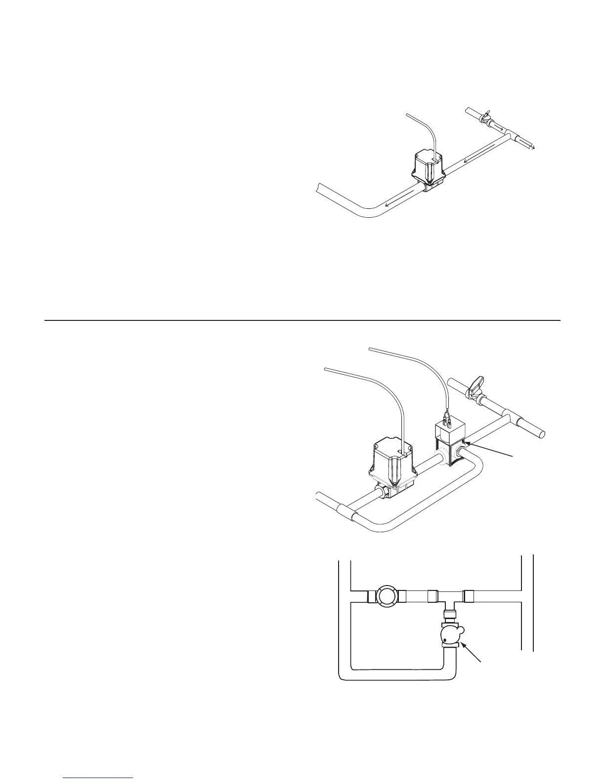
The servo valve installs in an unrestricted return line to the
inlet of the pump or directly into the tank. DO NOT install the
servo valve closer than 12” to the flowmeter. The servo valve
has a flow direction decal on it. Make certain that the actual
flow direction matches the decal on the servo valve. Do not
install the servo valve in the agitation line. Slow response
time and marginal operation may result. The return line
should tee from the main line just after the throttling valve.
See Illustration 17. The throttling valve is used to limit the
output (set maximum output) of the pump to the flowmeter
and servo valve. The throttling valve is adjusted to put the
servo valve in its optimal operating range. Please refer to
Pre-Field System Checkout for proper valve adjustment
procedure.
The servo valve connects directly from the module to the
3-pin W/P connector (NO tie). If more length is required, use
a 3-pin W/P extension cable of the appropriate length. If
using a Braglia or other 12-volt control valve, please refer to
Appendix C.
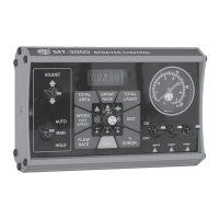
Relief Valve
The relief valve is used to “dump” pressure when all boom
valves are turned off. Whenever all the boom control
switches are turned off, or when HOLD is selected with the
master switch, the relief valve should be open. Use this
plumbing illustration (See Illustration 18) as your pattern
for proper installation if your relief valve has a flow-through
port. DO NOT install the relief valve closer than 12” to the
flowmeter. Locate a 2-pin solenoid cable and connect it to
the relief valve using an appropriate method. Connect a
2-pin M/P connector to the module cable with no colored
tie. Be careful not to connect the relief valve cable to one
of the boom shut-off leads. All of the boom shut-off leads
have a colored tie near the 2-pin M/P connector. The relief
solenoid lead does not.
If all valves are NOT the same type (all solenoid or all ball
valves), refer to Appendix B for wiring instructions.
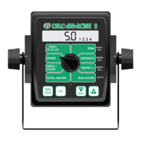
If your relief valve does not have flow-through port, you must
add a “T” fitting. See Illustration 19.
NOTE: To as sure a good con nec tion and avoid corrosion,
coat electrical connections with sil i cone grease.
17
Illustration 18
Illustration 19
Illustration 17
“T” Fitting
Servo
Valve
Relief
Solenoid
Return to pump
inlet or unrestricted
return to tank
Servo Valve Cable
Fr om Pump
Throttling Valve
T o Flowmeter
Servo Valve
Installation (cont)
Servo, Throttling Valves
NOTE: The servo valve may be installed in the main spray
line (in-line). For in-line use, you will need to calibrate for
in-line (see Calibration section). Failure to set for in-line will
result in backwards operation of the servo valve.