47
Using Ball and Solenoid Valves
The MT-3405 M can be set up to use ball valves for the booms and a solenoid valve for the relief. Install as shown:
Appendix B
Various Ball Valve Configurations
The MT-3405M system is equipped with a 2-conductor cable with connector and jumper cover. Install jumper cover for
solenoid valves. Remove jumper cover for ball valves.
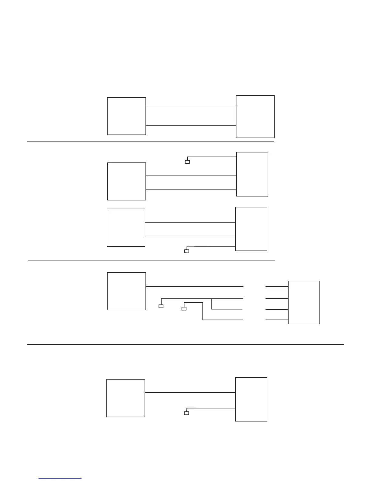
Some basic 2, 3 & 4-wire configurations are shown below. If you need assistance for wiring other than shown, contact Micro-
Trak for wiring instructions.
A
B
Valve
Switching Wires*
M/P
150
A
B
M/P
150
12-volts
+
Valve
Switching Wires*
A
B
Red
Black
Red
Black
White
M/P
150
Ground
Spraying
Systems
344E &
344AE-2
Switching Wires*
M/P
150
A
B
Valve
Switching Wire
12-volts
Ground
Relay +
Relay –
Motor –
Motor +
–
+
2-Wire Valve
3-Wire Valve
4-Wire Valve
Micro-Trak Boom Connection
(Set for ball valve -
jumper cover removed).
Micro-Trak Boom Connection
(Set for ball valve -
jumper cover removed).
Micro-Trak Boom Connection
(Set for ball valve -
jumper cover removed).
Micro-Trak Boom Connection
(Set for solenoid valve -
jumper cover installed).
* If valve runs backwards, reverse switching wires.
A
B
M/P
150
Ground
Relief or
boost
solenoid
valve
Micro-Trak Boom Connection
(Set for ball valve -
jumper cover removed).