If there is no response from any of the following tests, refer to
the main Wiring Diagram on the next page to locate the next
connector in line to ward the con sole and repeat the test at
that con nec tor. If there is a response at that connector, the
problem may be in the cable between the two connectors
(or the con nec tors themselves).
SPEED INPUT
Turn rotary dial to speed po si tion and dis con nect the
speed sensor (yel low tie) from the main harness. Check
for 12 volts between pins B (white) and C (black) of the
main harness speed cable (yellow tie). Using a clip lead
or other jumper wire (such as a paper clip bent in a “U”),
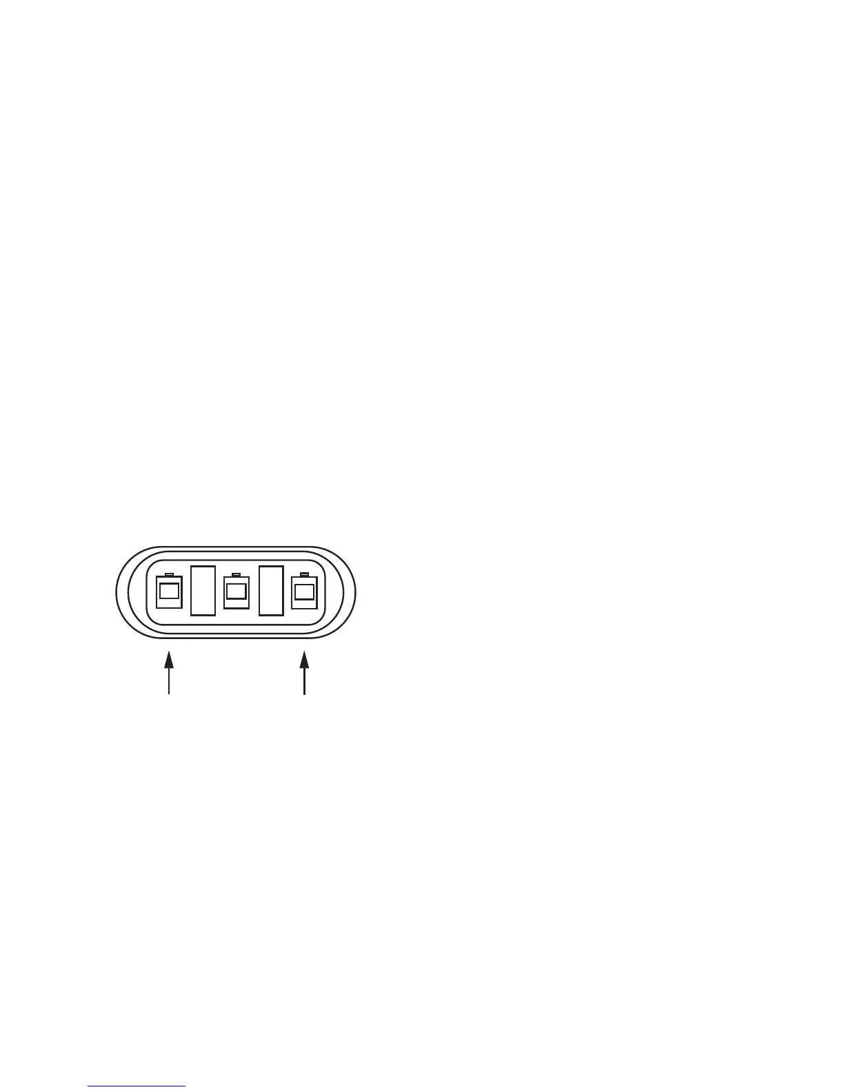
several times rap id ly short to geth er pins A (red) and C
(black) of the 3-pin connector (See Illustration 36). The
console should respond with some speed read ing.
FLOW INPUT
Turn rotary dial to flow rate (not spray rate) and disconnect
the flow sen sor (green tie) from the main harness. Check
for 12 volts be tween pins B (white) and C (black) of the
main harness flow cable (green tie). Using a clip lead or
other jumper wire (paper clip bent in a “U”), several times
rapidly short together pins A (red) and C (black) of the
3-pin connector (See Illustration 36). The con sole should
re spond with some flow rate reading.
REMOTE RUN/HOLD INPUT
Disconnect the remote run/hold sensor (or jumper cover)
from the main harness. Check for 12 volts between pins
B (white) and C (black) of the main harness remote
run/hold cable (gray tie). With the consoles Run/hold
switch in RUN, place a clip lead or other jumper wire
(such as a paper clip bent in a “U”) between pins A (red)
and C (black) of the main harness run/hold connector
(gray tie) should turn off the “HOLD” indicator on the
console display. Removing the jumper should turn on
the “HOLD” indicator on the console display.
FLOWMETER
Shaking the Flowmeter end to end should pro duce a “rattling”
sound (shaft end play). Blowing in the meter from either end
should spin the turbine freely. If the turbine spins freely but
the meter will not register flow with a known working sensor,
the turbine may be defective. See Appendix D for Flow me ter
Clean ing and Assembly details.
39
Troubleshooting (cont)
Console Inputs
ELECTRIC BOOM VALVES
To configure your system to use 2-wire motorized ball valve
shut-offs, remove the jumper cover from the 2-pin connector
on the main console harness. See Wiring Diagram on the next
page. If you are using solenoid valves, do not remove jumper
cover. If 12 volts are present between the two harness
wires to valves, but valves will not activate, consult valve
manufacturer’s troubleshooting instructions.
SERVO VALVE CONTROL SIGNAL
Flip the power switch to ON, put the console in MANUAL
mode, place the Run/Hold switch in the RUN position and
turn all boom switches to ON. Using a voltmeter, check
from a good frame ground to each of the servo wires on
the main harness connector. There should be about six
volts on each wire. Holding the “+” button should cause
one wire on the three-pin connector to pulse from six
toward four volts and the other wire on the three-pin
connector to pulse from six toward eight volts. Holding
the “-” button should show the opposite results.
SERVO VALVE
The best way to test the servo valve is with a known working
console. Flip the power switch to ON, put the console in
MANUAL mode, place the Run/Hold switch in the RUN
position and turn all the boom switches to ON. With the
servo valve connected to the servo valve lead on the main
harness, holding the “+” button should close the servo valve
and holding the “-” button should open the servo valve
(provided the console has passed the Servo Valve Control
Signal test).
NOTE: The opposite should result if calibrated for inline.
The servo valve should operate smoothly from fully open
to fully closed, in both directions.
You may also use a 9-volt transistor battery. Connecting the
battery to each terminal on the servo valve should cause the
servo valve to run in one direction. Reversing the battery
connections should cause the servo valve to run the other
direction. The servo valve should operate smoothly from end
to end, in both directions. DO NOT connect 12 volts directly
to the servo valve. Damage may result.
PLUMBING
Proper plumbing is a very important factor in obtaining
optimal performance from your MT-3405M system. The chart
on page 41 will help you determine what area of the plumbing
may be causing your problem. At this point, it is assumed that
your plumbing basically matches that of the System Diagram
on page 20 and that the servo valve and flowmeter are
known to be installed correctly and functioning properly. In
addition, make certain that you have selected and installed
the correct spray tips for the application, speed and spray
rate that you intend to maintain. Don’t forget the obvious
such as leaky fittings and hoses, pinched hoses and plugged
or worn nozzles. If you need more detail than the chart
provides, please refer to Plumbing Guidelines on pages 43
and 44.
PRESSURE SENSOR
The only way to field test the pressure sensor is to connect
it to a known working console, apply pressure and verify the
correct pressure reading on the console display.
The pressure sensor is a 4-20 mA (industry standard).
Three-Pin Connector
Illustration 36