RED cable tie near the connector. Boom three (3) connects
to the mating connector with the ORANGE cable tie near the
connector. Boom four (4) connects to the mating connector
with the YELLOW cable tie near the connector. Boom five (5)
connects to the mating connector with the GREEN cable tie
near the connector. See Illustration 20.
NOTE: To configure your system using 2-wire motorized
ball valve shut-offs, remove jumper cover from the
2-conductor cable exiting the back of the MT-3405 M
console. If using this system with 3-wire or 4-wire motorized
ball valve shut-offs, see Appendix B.
Plumb boom valves with flow-through port as shown.
Boom valves of differing designs may require a “T” fitting.
See Illustration 20. Make certain to use adequately sized
plumbing lines to avoid ex ces sive pressure drops. DO NOT
install the shut-off valves closer than 12” to the flowmeter.
Locate the boom shut-off cables. Crimp the insulated female
quick disconnect terminals provided with the cables to
both wires. (If valves have wires, crimp mating terminals on
those wires). Attach the cables to the terminals on the boom
valves. Normally, wires connect red to red and black to black.
If valves operate backwards, reverse connections. Apply
silicone grease to the ter mi nal connections to help prevent
corrosion and insure a good electrical con nec tion.
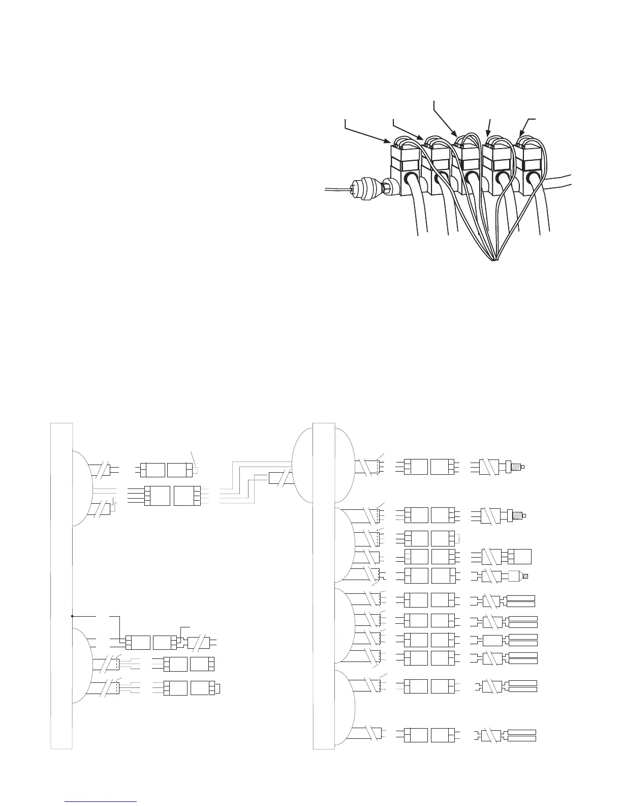
Locate the colored cable ties included with the boom
shut-off cables. Attach a BROWN tie near the 2-pin M/P
connector on the boom one (1) cable. Attach a RED tie near
the 2-pin M/P connector on the boom two (2) cable. Attach
an ORANGE tie near the 2-pin M/P connector on the boom
three (3) cable. Attach a YELLOW tie near the 2-pin M/P
connector on the boom four (4) cable. Attach a GREEN tie
near the 2-pin M/P connector on the boom five (5) cable.
Connect the 2-pin M/P connectors to the mating con nec-
tors on the module. Boom one (1) connects to the mating
connector with the BROWN cable tie near the connec tor.
Boom two (2) connects to the mating connector with the
Boom 1
(brown tie)
Boom 2
(red tie)
Boom 3
(orange tie)
Boom 4
(yellow tie)
Boom 5
(green tie)
18
Illustration 20
Installation (cont)
Boom Shut-off Valves
BROWN TIE
BOOM THREE
BOOM FOUR
BOOM TWO
FEMALE .250 Q.D.
BOOM ONE
RED TIE
ORANGE TIE
YELLOW TIE
RED
BLACK
RED
BLACK
GREEN TIE
GRAY
FLOW
SERVO
PRESSURE
RUN/HOLD
RUN/HOLD
SPEED
CHASSIS GROUND
NATURAL TIE
YELLOW TIE
GRAY TIE
YELLOW TIE
SPEED
A
B
2-PIN
M/P 150
TOWER
BOOM FIVE
RED
BLK
MT-3405 M CONSOLE
REMOVE JUMPER COVER
TO CONFIGURE FOR BALL VA LVES.
GREEN TIE
ORANGE, BATTERY +
BLUE, BATTERY –
BLUE
FEMALE .250 Q.D.
FEMALE .250 Q.D.
RELIEF/MASTER
SC-3405 MODULE
A
B
A
B
C
D
A
B
C
D
2-PIN
M/P 150
SHROUD
4-PIN
SQUARE
4/P
TOWER
4-PIN
SQUARE
4/P
SHROUD
ORG
BLU
BLK
RED
ORG
BLU
BLK
RED
A
B
C
RED
WHT
BLK
A
B
C
3-PIN
M/P 150
TOWER
3-PIN
M/P 150
SHROUD
3-PIN
M/P 150
SHROUD
RED
WHT
BLK
A
B
C
A
B
C
A
B
C
A
B
C
A
B
C
A
B
C
3-PIN
M/P 150
TOWER
3-PIN
M/P 150
TOWER
3-PIN
W/P 150
TOWER
3-PIN
W/P 150
SHROUD
3-PIN
M/P 150
SHROUD
3-PIN
M/P 150
SHROUD
RED
WHT
BLK
RED
WHT
BLK
RED
BLK
RED
BLK
RED
BLK
RED
BLK
RED
BLK
RED
BLK
A
B
A
B
A
B
A
B
A
B
A
B
A
B
A
B
A
B
A
B
2-PIN
M/P 150
TOWER
2-PIN
M/P 150
TOWER
2-PIN
M/P 150
TOWER
2-PIN
M/P 150
TOWER
2-PIN
M/P 150
TOWER
2-PIN
M/P 150
SHROUD
2-PIN
M/P 150
SHROUD
2-PIN
M/P 150
SHROUD
2-PIN
M/P 150
SHROUD
2-PIN
M/P 150
SHROUD
2-PIN
M/P 150
SHROUD
RED
BLK
A
B
A
B
2-PIN
M/P 150
TOWER
2-PIN
M/P 150
SHROUD
RED
BLK
A
B
A
B
2-PIN
M/P 150
TOWER
2-PIN
M/P 150
SHROUD
RED
WHT
BLK
RED
WHT
BLK
A
B
C
3-PIN
W/P 150
SHROUD
RED
BLK
RED
BLK
RED
BLK
RED
BLK
RED
BLK
FEMALE .250 Q.D.
FEMALE .250 Q.D.
FEMALE .250 Q.D.
FEMALE .250 Q.D.
FEMALE .250 Q.D.
FEMALE .250 Q.D.
FEMALE .250 Q.D.
FEMALE .250 Q.D.
FEMALE .250 Q.D.
3-PIN
M/P
TOWER
ORG
BLU
A
B
C
A
B
C
A
B
C
A
B
C
A
B
C
A
B
C
3-PIN
M/P 150
TOWER
3-PIN
M/P 150
TOWER
3-PIN
M/P
SHROUD
3-PIN
M/P 150
SHROUD
3-PIN
M/P 150
SHROUD
RED
WHT
BLK
RED
WHT
BLK