WIDTHBOOM
SELECT
TEST
SPEED
TARGET
RATE
ADJUST
RATE
CIRC
FLOW
CAL
SPEED
DISTANCE
TOTAL
FLOW
TOTAL AREA
PRESSURE FLOW RATE
SUB AREA
ON
OFF
ON
OFF
12345
B O O M S
RUN
HOLD
CAL
AUTO
MAN
RESET
MT-3405 M
™
AUTOMATIC RATE CONTROLLER
MANAUTO
CALHOLD
V 1 2 3 4 5
MIN
FLOW/
PRESSURE
APP. RATE
Place the console in HOLD.1.
Press and hold the “CAL” key for three sec onds to select 2.
the cal i bra tion mode. The con sole indicator will read
“CAL”, and the red warn ing light will flash.
Turn the rotary dial to the desired “CAL” po si tion. Then 3.
use the “+” and “-” keys to adjust the dis played val ue up
or down as needed. Adjust ALL necessary values. See
Illustration 23.
Hold the “CAL” key again for three sec onds to exit 4.
calibration. “CAL” will disappear from the dis play, and
the red warning light will turn off.
The display will flash alternately be tween distance and wheel
circumference when in the CIRC po si tion, or total flow and
flowmeter cal i bra tion when in the FLOW CAL position. When
“+” or “-” is pressed, the display will “hold” the item that was
displayed when that key was pressed. The display will resume
alternations after 64 seconds of no key being depressed.
Please refer to “Entering Calibration Values,” “DISTANCE/
CIRC” or “TOTAL FLOW/FLOW CAL” for details.
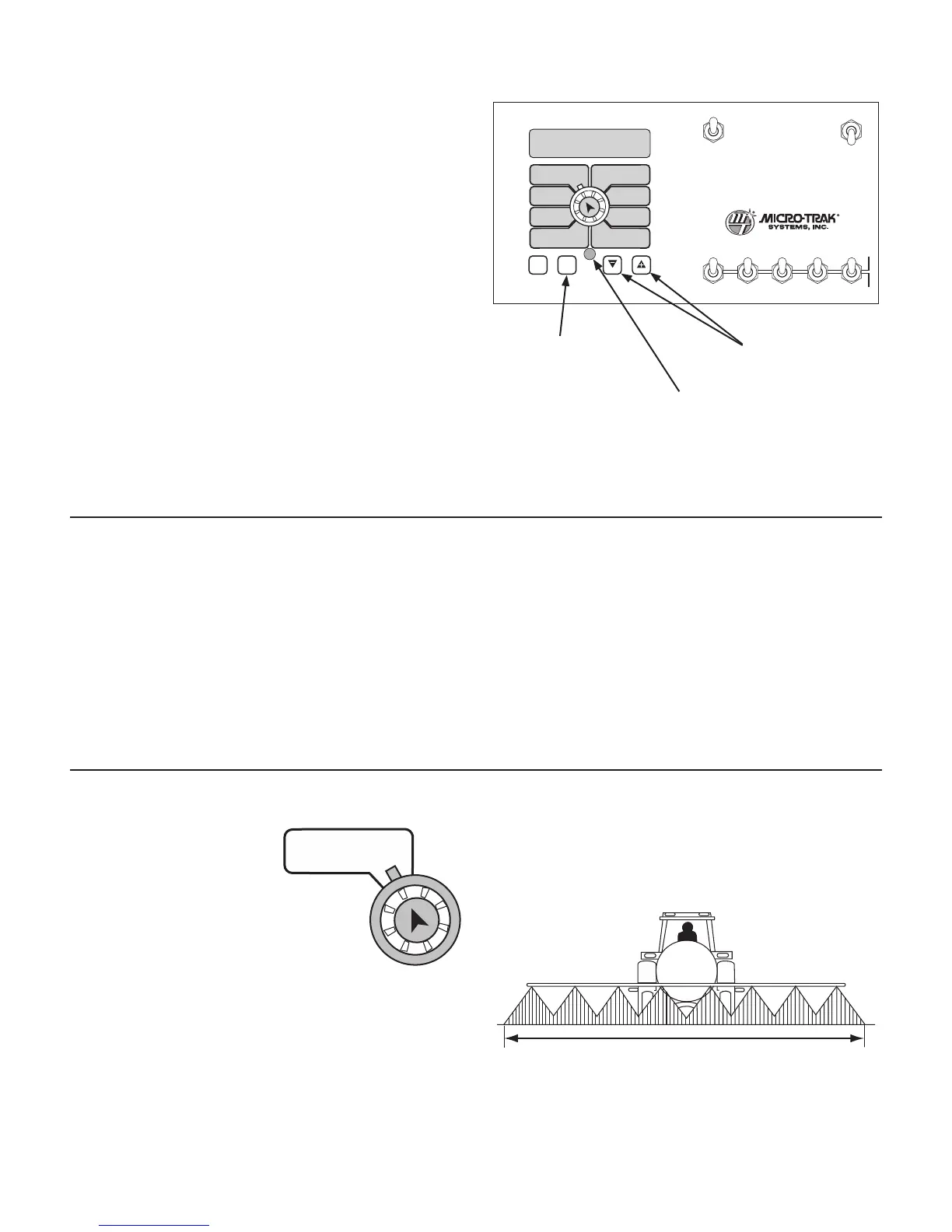
Press to enter or exit
calibration mode.
Press to increase or
decrease values.
Red warning light will
flash when in CAL.
Entering Calibration Values
To enter or change any of the system’s calibration values,
you must enter calibration mode. To enter calibration
mode, STOP the vehicle, place the run/hold switch on
the front panel in HOLD and press and hold the CAL
button until the “CAL” indicator lights up (approximately
three seconds).
NOTE: Calibration may be entered while moving, but this
is not rec om mend ed.
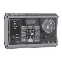
BOOM SEL: This po si tion is used to select the boom
sec tion to be cal i brat ed. With the ro ta ry dial in this po si-
tion, the dis play will show
the ac tive boom section
num ber. Use the “+” and
“-” buttons to select the
boom section to be calibrated. Once the
desired boom section has been selected, turn
the rotary selector to width to enter the effec-
tive work ing width for that boom section.
Re peat this pro ce dure for each boom section.
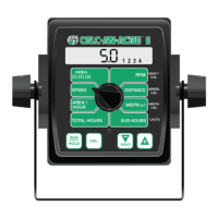
Setting Individual Boom Width
In order to accurately measure the number of gallons applied
per acre it is important to determine the correct “working”
width. The “working” width is the width of ground being
affected by any operation. This should be measured to the
nearest inch (millimeter).
25
Calibration (cont)
Entering Calibration
Illustration 23
NOTE: To verify which material units mode you are in, refer
to the Standard Factory-Loaded Calibration Values chart
on page 32.
Working Width
The console will remain in calibration mode, with the
RED warning light flashing, until you exit calibration or
turn off power.
Once in calibration mode, you may change any one, all or
none of the values, in any order.* To select a calibration
position, simply turn the rotary selector to the desired
position. Calibration positions are to the outside of the
rotary positions, in white lettering with red outlined boxes.
All values are adjusted using the “+” and “-” but tons on the
front panel.
IMPORTANT NOTE: Test speed must be last.
Your “working” width will vary depending on the type of
equipment you are using and the method of application.
For example, if you are broadcast applying chemicals your
“working” width will be the number of nozzles times the
nozzle spacing in inches (meters). For example, if you have 20
nozzles spaced at 20 inches, the working width is 400 inches.
See Illustration 24.
Illustration 24