OONN--BBOOAARRDD UUSSBB PPRROOGGRRAAMMMMEERR
Figure 14.
JP2 jumper
explanation
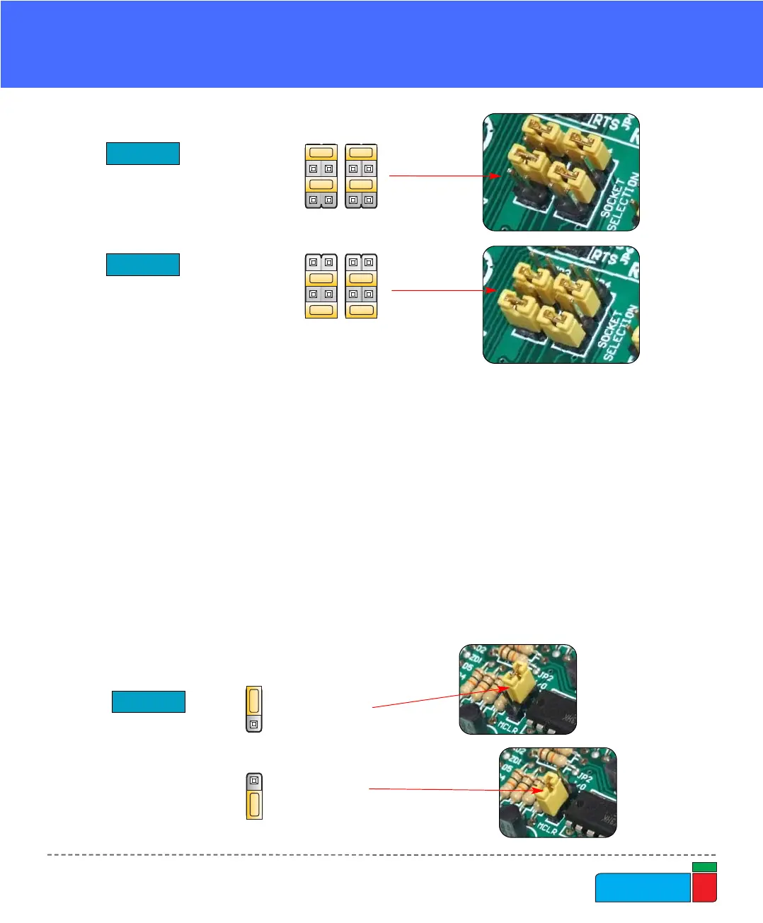
Jumper JP2 allows using the MCLR pin as RESET or as digital I/O. It can be RE3,
RA5 or RA3 pin depending on MCU that you are using.
When JP2 is in the lower position the hardware reset (pressing reset button) is
enabled and MCLR pin can not be used as an I/O pin.
When JP2 is in the upper position the MCLR pin can be used as an I/O pin but the
hardware reset is disabled.
When using DIP40, DIP28, DIP18A and DIP18B sockets, jumpers JP3 and JP4
should be in the upper position (default) as shown in Fig. 12.
For DIP20, DIP14 and DIP8 sockets, these jumpers should be in the lower position
(Fig. 13).
Figure 12.
Figure 13.
JP3 and JP4 for DIP40,
DIP28, DIP18A and DIP18B
JP3 and JP4 for DIP20,
DIP14 and DIP8