AANNAALLOOGG TTOO DDIIGGIITTAALL CCOONNVVEERRTTEERR IINNPPUUTT
A-D CONVERTER INPUT
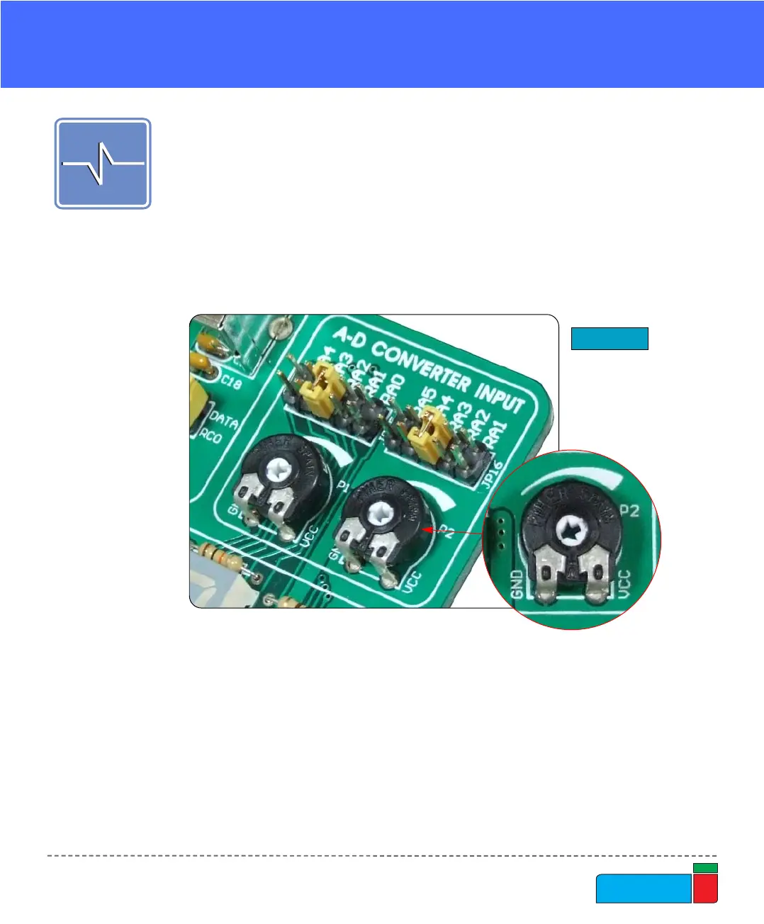
Figure 44.
A-D Converter input
EasyPIC4 development board has two potentiometers for working with Analog to
Digital Converter (ADC). Both potentiometers outputs are in the range of 0V to 5V.
Two analog signals can be connected on two different analog input pins at the same
time. The jumpers group JP15 enables connection between potentiometer P1 and
one of the following pins: RA0, RA1, RA2, RA3 or RA4. The jumpers group JP16
enables connection between potentiometer P2 and one of the following pins: RA1,
RA2, RA3, RA4 or RA5.
In order to measure analog signal without interference, turn the coresponding switch
on SW1 to OFF position. This will disable connection of the used PORTA pin to the
pull-up/down resistors.
Applications of A-D Conversion are various. Microcontroller takes analog signal
from its input pin and translates it into a digital value. Basically, you can measure
any analog signal that fits in range acceptable by PIC. That range is 0V to 5V.