EasyPIC4 User’s Manual
2244
page
MIKROELEKTRONIKA SOFTWARE AND HARDWARE SOLUTIONS FOR THE EMBEDDED WORLD
MikroElektronika
Development
tools
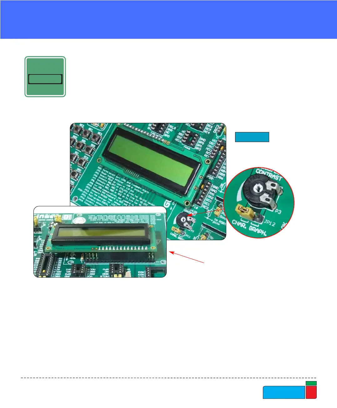
The LCD must be placed in the marked position with two free pins to the left and
four free pins to the right. It is important to note that the LCD should be placed or
removed from EasyPIC4 only when the power is off. Before attaching the LCD, set
jumper JP12 to the left position. The LCD's contrast can be adjusted using poten-
tiometer P3 which is located to the right of the GLCD/LCD connector.
LLCCDD 22XX1166 IINN 88--BBIITT MMOODDEE
LCD 2X16 IN 8-BIT MODE
When using a character LCD in 8-bit mode, the connector that is shared with the
GLCD should be used. Since this connector has 20 pins and the character LCD has
only 14 pins, special attention is required when placing the LCD. Otherwise the
LCD can be permanently damaged.
Figure 33.
LCD 2x16 in 8-bit mode
NOTE: Special attention is required when placing the LCD. Otherwise the LCD can
be permanently damaged.
View from the back:
shows which pins
stays disconnected.