SWITCHES
The EasyPIC4 development board features a number of peripherial devices. In
order to enable these devices before programming, you need to check if appropri-
ate jumpers or switches have been properly set.
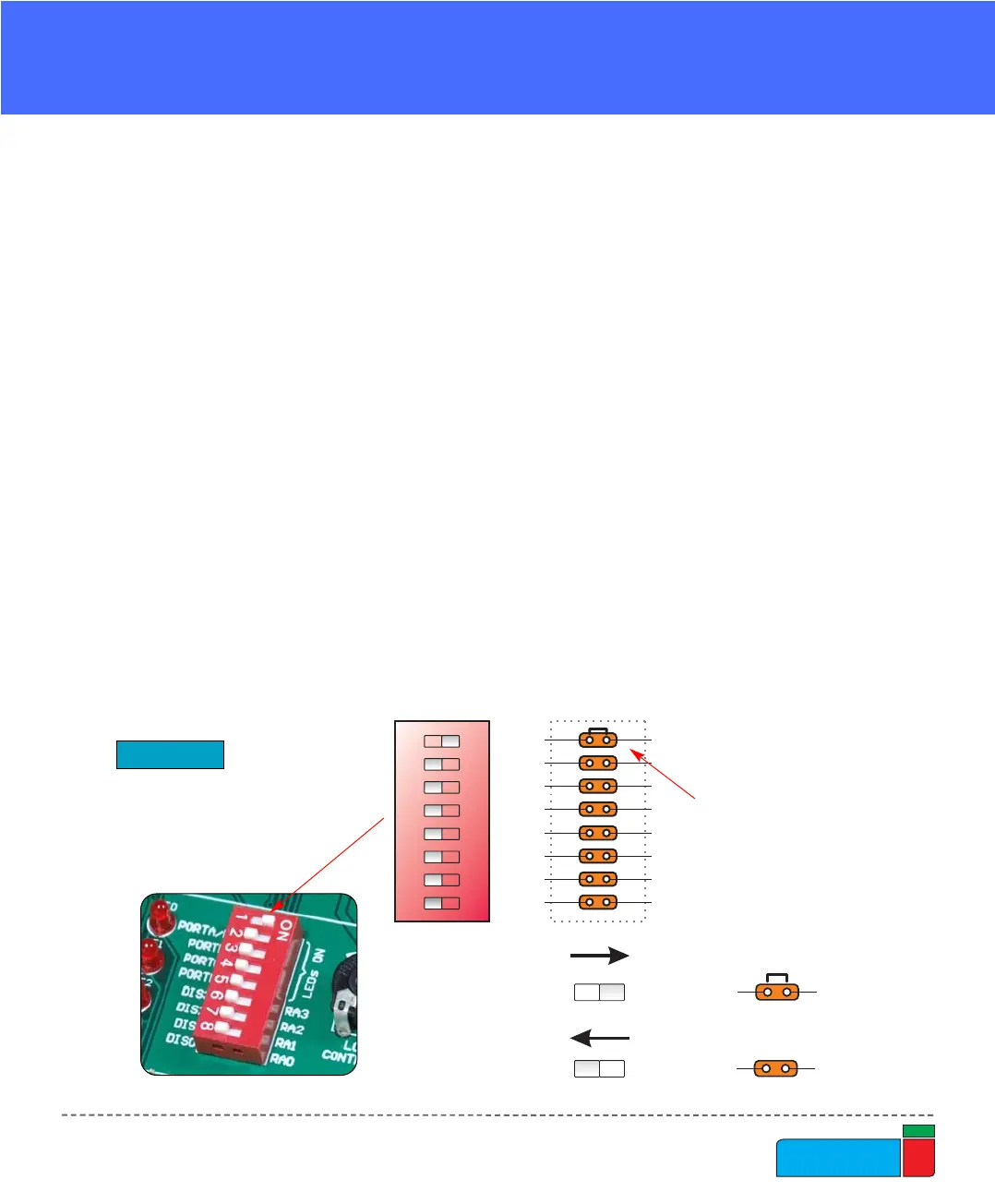
Switches are devices that have two positions - ON and OFF, which have a role to
establish or break a connection between two contacts. The EasyPIC4 development
board has two groups of switches.
The first group, SW1, enables connections between the microcontroller port with
analog capabilities (PORTA) and external pull-up/down resistors. The pull-up/down
resistors should be disconnected from the analog input pins, otherwise they will
affect the input voltage level. When PORTA pins are used as digital inputs/outputs,
the appropriate pull-up/down resistors should be enabled.
The upper four switches of SW2 are used to enable LEDs connected to PORTA/E,
PORTB, PORTC and PORTD. For example, if the switch for PORTB is OFF, all
PORTB LEDs will be turned off.
The lower four switches of SW2 are used to enable the 7-segment displays. If you
don’t need the 7-segment displays in your project, these switches should be OFF.