EasyManua.ls Logo

MicroElektronika EasyPIC4 - USB Communication Setup

Default Icon
34 pages
Print Icon
To Next Page IconTo Next Page
To Previous Page IconTo Previous Page
Loading...
EasyPIC4 Users Manual
MIKROELEKTRONIKA SOFTWARE AND HARDWARE SOLUTIONS FOR THE EMBEDDED WORLD
2277
page
MikroElektronika
Development
tools
EasyPIC
ICD
4
UUSSBB CCOOMMMMUUNNIICCAATTIIOONN
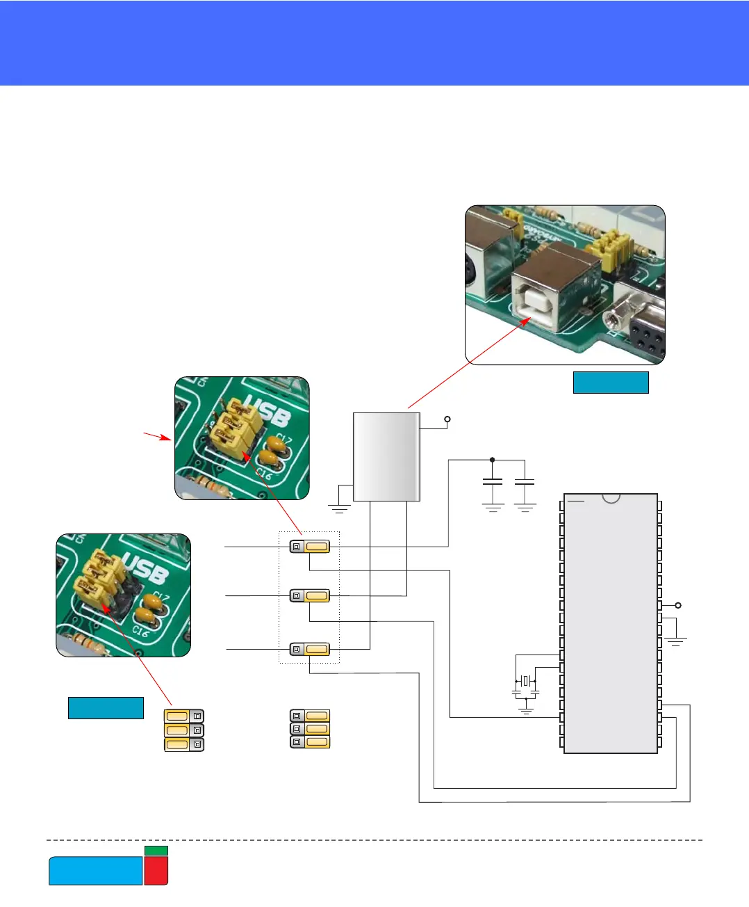
The USB communication connector is placed in the upper right corner of the
EasyPIC4. It is used with specific PIC microcontrollers that have USB support, such
as PIC18F2450 or PIC18F4550. Note that the USB communication connector can-
not be used for programming and that the USB
programming connector cannot be used for
communication. In order to enable connection
between the microcontroller and USB commu-
nication connector, the JP9 jumpers group
should be set to the right position. As the result,
microcontroller pins RC3, RC4 and RC5 are dis-
connected from the rest of the system and con-
nected to the USB communication connector.
USB COMMUNICATION
RC4-U
RC4
RC5-U
RC5
RC3-U
100n
100n
RC3
VCC
JP9 JP9
RC3-U, RC4-U, RC5-U are
available to other peripherials
RC3-U, RC4-U , RC5-U are
connected onl to USBy
VCC
VCC
D+
D-
USB
PICxxxx
RA0
RA1
RA2
RA3
RC0
RC1
RA4
RA5
RE0
RE1
RE2
RC3
RD0
RD1
RC4
RD3
RD2
RC5
RC6
RC7
RD4
RD5
RD6
RD7
RB0
RB1
RB2
RB3
RB4
RB5
RB7
RB6
RC2
VDD
VSS
OSC1
OSC2
MCLR
VDD
VSS
X1
8MHz
C6
22pF
C7
22pF
JP9
Figure 37.
Figure 38.
USB communica-
tion schematics
USB communication connector
To enable USB
communication all
three jumpers have
to be set to the right
side.