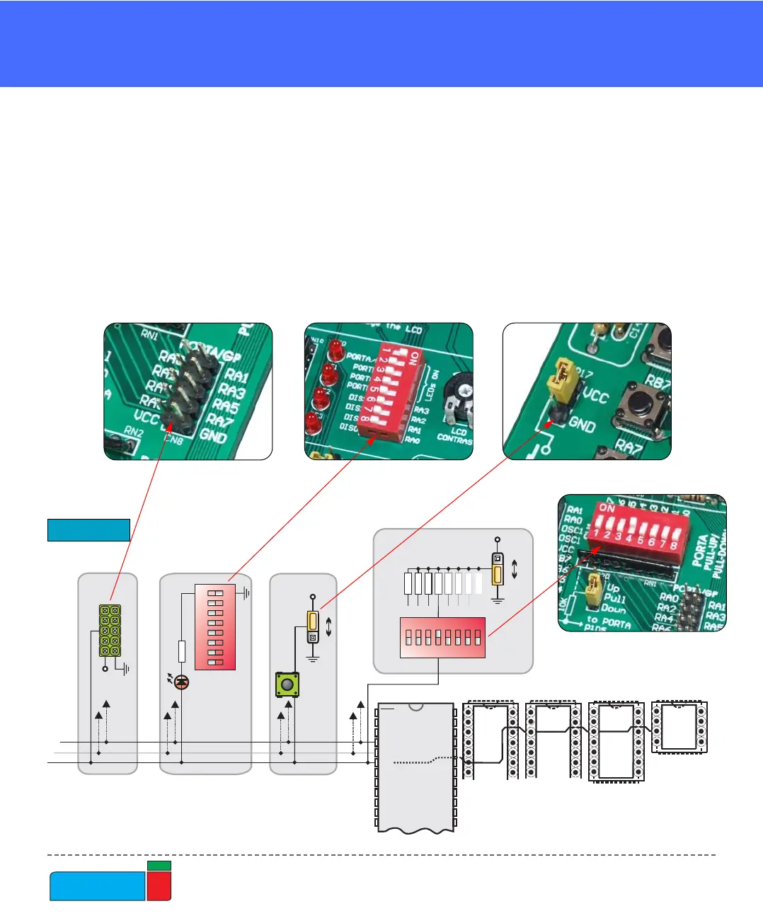
Microcontroller’s pins are routed to various peripherals as illustrated in Fig. 6. All
ports have direct connections to Direct Port Access connectors. Such connectors are
typically used for connecting external peripherals to the board or for providing use-
ful points for connecting digital logic probe.
All ports are connected to LEDs, push-button switches and pull-up/down resistors,
which allow easy monitoring and testing of digital pin state .
Some pins are connected to other peripherials such as the DS1820 temperature sen-
sor, RS-232 communication, 7-segment displays, LCD, etc.
System connection
Figure 6.
MMCCUU SSOOCCKKEETTSS