© Microhard Systems Inc. 22
3.0 Hardware Features
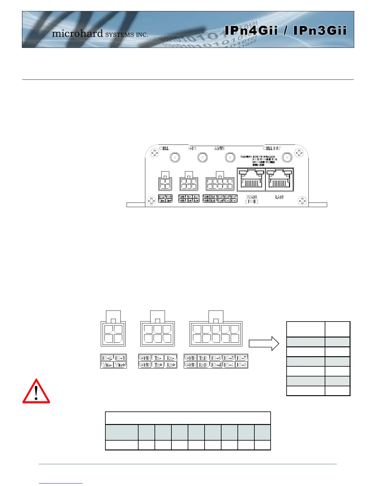
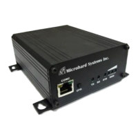
Drawing 3-5: IPnXGii Rear View
The Console (RS232 –Tx/Rx) on the rear of the unit is used for:
AT Command Interface
RS232 serial data (TX, RX)
The RS422/485 Port is a standalone port that can be used in addition to the RS232 Data Port.
Programmable I/O– The IPnXGii has 8 programmable Analog/Digital Inputs or 8x Digital Outputs.
Maximum recommended load for the output pin is 150mA @ 30 Vdc (Vin).
Vin+/Vin– is used to power the unit. The input Voltage range is 9-30 Vdc.
PoE– The IPnXGii can also be powered using Passive PoE on the Ethernet
Port (WAN), via a PoE injector.
3.1.2 Connectors and Indicators
3.1.2.2 Rear
On the back of the IPnXGii is the Console port (RS232 - Rx/Tx), RS485/422 interface, Programmable I/O,
Dual Ethernet Ports (WAN/LAN) as well as the power connections. The unit also has the SMA(F)
connectors for the Main (TX/RX), the Diversity (RX) antenna’s, and a RP-SMA Female connector for ANT3
Name
Input or
Output
Tx+ O
Tx- O
Rx+ I
Rx- I
Vin -
Vin + I
Table 3-4: Data RS422/485,
Vin Pin Assignments
Caution: Using a power
supply that does not
provide proper voltage
may damage the modem.
Ethernet RJ45 Connector Pin Number
Source
Voltage
1 2 3 4 5 6 7 8
9 - 30 Vdc Data Data Data DC+ DC+ Data DC- DC-
Table 3-5: Ethernet PoE Connections