© Microhard 16
2.0 Quick Start
2.2 Simple Master and Slave - Auto (Using Defaults)
This Quick Start example requires (2) pMDDL units, one will be configured as a
Master (M), the second unit will be configured as a Slave/Remote (S). This example
will use factory defaults to set up each unit so that a simple network will be estab-
lished.
✓ Use Section 2.1 Getting Started to power up a pair of pMDDL modules mounted
in a Pico Ethernet Motherboard.
✓ Master: Once the pMDDL is fully booted (solid blue CPU LED), press and hold
the CFG button. Once the CPU LED begins to flash, continue to hold for at least
10 seconds, then release.
✓ The pMDDL will then reset all settings to default values, and set the following
settings that are required to automatically create a link with a slave:
- IP Address: 192.168.168.1, Operating Mode: Master
- Network ID: MHK_Alpha, Channel Bandwidth: 8 MHz
- Channel-Frequency: 76 - 2477 MHz
✓ Slave: Ensure the pMDDL is fully booted (solid blue CPU LED), then press and
hold the CFG button. Once the CPU LED begins to flash, continue to hold for
5 seconds, then release.
✓ The pMDDL will then reset all settings to default values, and set the following
settings that are required to automatically create a link with a slave:
- IP Address: 192.168.168.2, Operating Mode: Slave
- Network ID: MHK_Alpha, Channel Bandwidth: 8 MHz
- Channel-Frequency: 76 - 2477 MHz
✓ Once both units have finished changing settings (~60 seconds) a wireless link
should automatically be established between them, this can be seen by observ-
ing the RSSI LEDS, they should be on solid, indicating a link (the more LEDs il-
luminated = stronger the link).
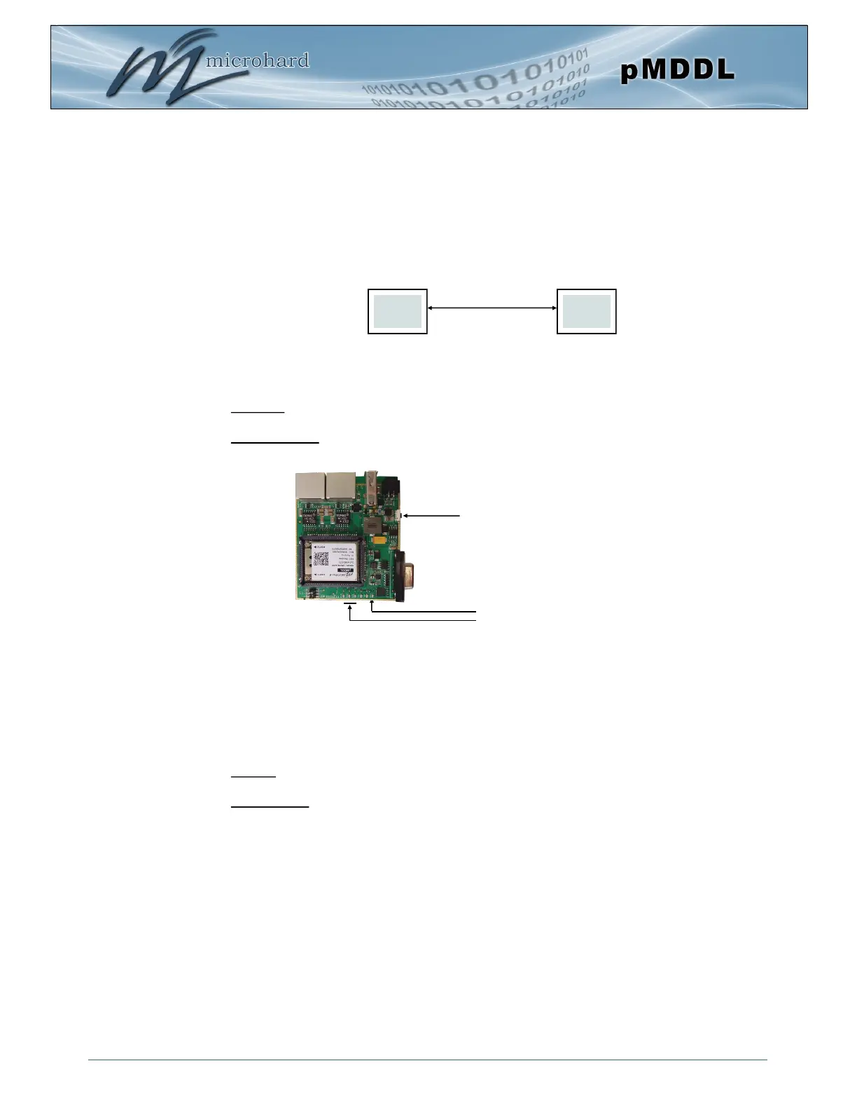
M S
Wireless
Press and hold CFG button for at least
10 seconds to reset to a default Master pMDDL
Press and hold CFG button for 5 seconds
to reset to a default Slave pMDDL
CPU LED (Blue)
RSSI LEDS (Green)