© Microhard 33
3.0 Hardware Features
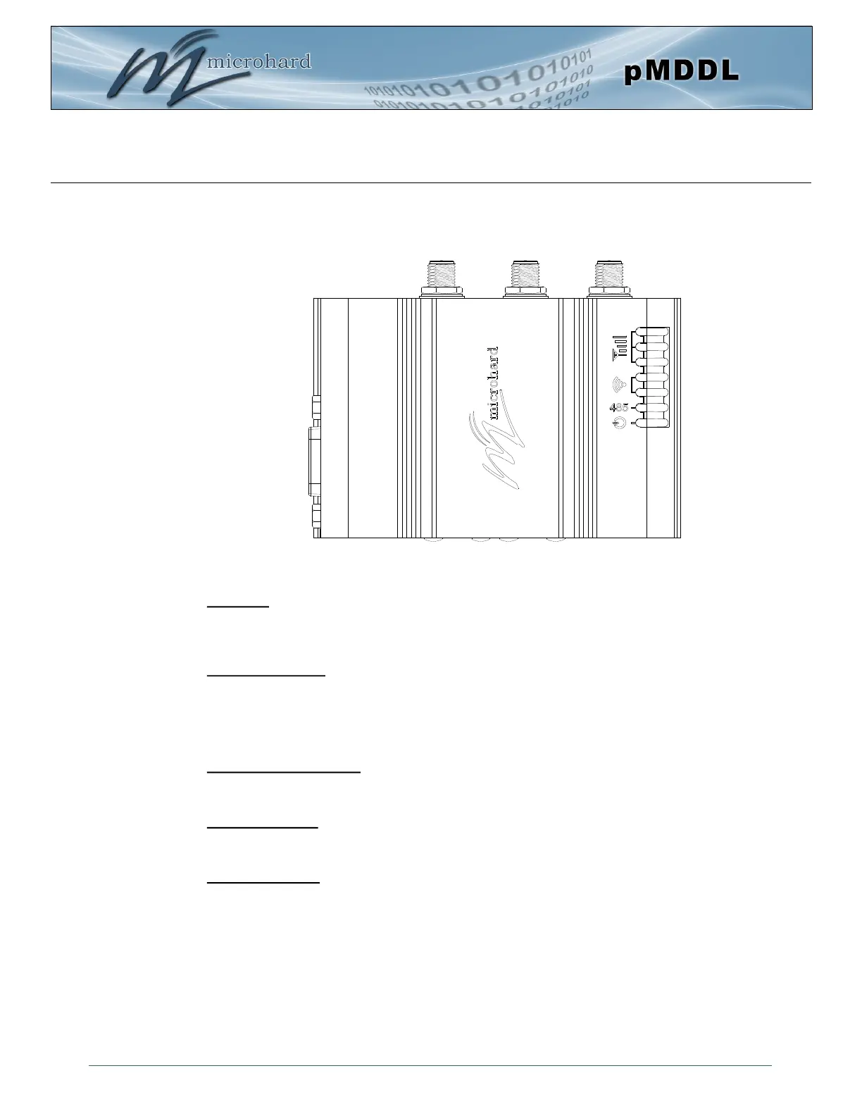
3.2.2 pMDDL-ENC Connectors & Indicators
Figure 3-1: pMDDL-ENC Top View
Ant 1 AUX Ant 2 (3x RP-SMA Female)
RSSI LEDs
TX/RX LEDs
CPU/Status
DE9 Female
Serial
Antennas:
The pMDDL-ENC module uses a RP-SMA Female connectors. ANT1 and ANT2 are marked on the
Enclosure. AUX is used to trigger an external amplifier as it goes high (3.3V) during TX.
RSSI LEDs (Green):
The RSSI LEDs indicate the Received Signal Strength on the Wireless Link. On a Master it will indicate an
average RSSI value based on connected units. On a Slave the RSSI LEDs will represent the signal
strength between the Slave and the Master it is connected to. (The more LEDs illuminated, the stronger the
signal)
TX/RX LEDs (Red/Green):
The TX/RX LEDs indicate wireless traffic to/from the pMDDL module.
RS485 LED (Blue):
The RS485 LED indicates that the serial port has been configured as a RS485 port.
CPU/Status (Blue):
The CPU/Status LED indicates that power has been applied to the module. A Solid LED indicates normal
operation, while flashing indicates boot or firmware upgrade status.
RS485 LED