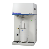
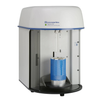
SediGraph III 5120 Service Card Cage and PCBs
Mar 2010 2-13
• The Fluid Control interface has circuitry to control the three valves and two pumps in
the Fluid module. The cell pump has an On/Off and direction bit. The cell has speed
control through a 12 bit DAC. The Mixing pump, waste valve, rinse valve and the air
valve have an On/Off bit. There is also a Status bit which reads the status of the pump
kill switch.
• Board ID EEPROM with I
2
C interface - this EEPROM is used to hold the board
identification and configuration information.
• MICBus interface - to connect the PCB with the rest of the instrument.
• Surface mount design, except for thru-hole connectors.
512/17703/011 Stepper & Heater Control PCB
This PCB controls the generation of stepper pulses and direction, handles heater control and
readings of the RTD, determines type of magnetic stirrer used, and monitors the status of the
cell limit switches. The stepper and heater control PCB features:
• 2X stepper motor control w/L297, L298N and L6210 chipset for speed, direction and
motor drivers. This board has two stepper motor channels to drive and control the cell
stepper and the mixer stepper motors. The cell stepper operates from 0 to 500RPM,
while the stirrer motor operates from 0 to 1000RPM. The cell stepper also has a
direction bit for Up/Down operation.
• 2X Heater control and drivers 4A @ 24VDC. Heater drivers are controlled by two
independent hardware control circuits. These read the RTD outputs to provide a control
loop. The temperature for each circuit is compared to the provided set-point. If the
temperature is out of range, an error signal is generated and the PWM output for each
heater driver is adjusted. This signal is a 24VDC PWM signal @ approximately 200Hz.
• 2X RTD temperature channels w/ADC for software reading. Two interfaces are
provided for the 2-wire 1000Ω RTDs used in this system. The temperature
measurement range is 0 to 60°C. The signals are buffered and amplified then fed to a V
to F converter for generation of either the mixing chamber temperature or Analysis
module temperature.
• Mixing Chamber interface. The PCB will be able to determine the type of mixing
chamber used by the 2 ID bits.
 Loading...
