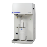
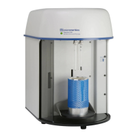
SediGraph III 5120 Service Card Cage and PCBs
Mar 2010 2-15
512/17708/011 Fluid Control PCB
The Fluid Control PCB has the controls for the two pumps, three valves, magnetic stirrer and
the mixer RTD. This PCB has the following features:
• There are two servo control 12-bit DACs and circuitry to control the pump speeds.
• There are three identical valve control circuits on the PCB. The valves have a relay for
directional control and R/C network to provide the initial surge current to move a valve
with a resistor to provide the holding current.
• Board ID EEPROM with I
2
C interface, this EEPROM is used to hold the board
identification and configuration information.
• Surface mount design, except for thru-hole connectors, and specialized components.
512/17709/011 Fluid Interconnect PCB
The Fluid Interconnect PCB is a cable interconnect board providing a single, convenient and
reliable connection point for the electric assemblies in the Fluid Control module. It provides a
direct slide-in connection to the stirrer module. The mixing chamber connector interfaces to
the new Mixer ID signals. This PCB is mounted inside the 5120 near the mixing chamber.
Card Cage Serviceable items
512/17701/011 Backplane PCB (board that CPU, I/O Control and the Stepper and Heater
PCB connects) integral part of the card cage
300/17700/011 i386 CPU PCB (first PCB from the right hand side)
512/17702/011 I/O and Control PCB (second PCB from the right hand side)
512/17703/011 Stepper & Heater Control PCB (third PCB from the right hand side)
512/17704/011 X-ray and PMT control PCB (located on the PMT side of the Analysis
module)
512/17708/011 Fluid Control PCB (located on the back side of the card cage)
512/17709/011 Interconnect PCB (located in the fluid module; this is where the mixing
chamber, valves and pumps connect)
.
 Loading...
